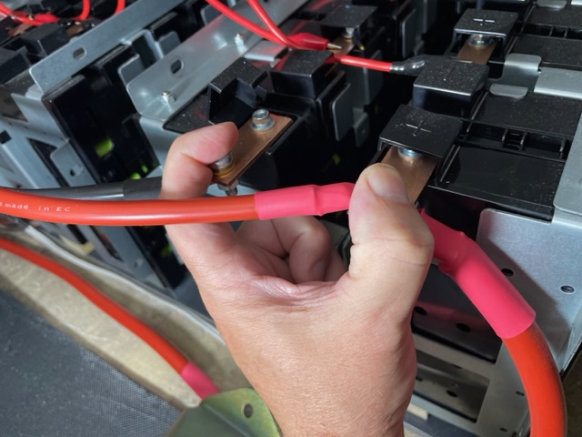
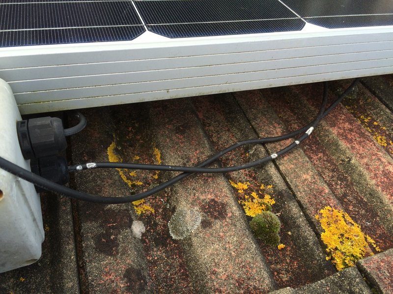
I need to extend one of my PV cable pairs about 4m, which leads to the question "what is the right way to join a DC PV cable"? Given the requirement for double-insulation can I just use a copper butt crimp to join the two ends and then put two layers of heat-shrink over it? Or maybe better heat-shrink, some physical protection and a bit more heatshrink? I could just use a pair of MC4s, which are designed for this application, but they don't have a great rep, so I thought an insulated butt-crimp would actually be a more reliable, lower-resistance connection. Max current (Iscmax@60C) is 14.5A Thoughts?
It's 4mm cable.
And another thing I don't really understand. All the specs for DC isolators tell you to get one rated to to 125% of the short-circuit current. So the 16A DC isolator I have for a circuit with an Iscmax of 14.3A which you might think would be adequate, officially isn't. It should be > 17.9A, which in practice means a 20A one.
Does anyone know where this +25% comes from? Is it the wiring regs or some random safety factor everone uses, or an MCS recommendation? Or is this a simple-minded way of allowing for the thermal co-efficients? My panels string Isc is 14.07A, and the temp coefficient for Isc is 0.050%/C, so at 60C that's ~1.5% change in current, (i.e. 14.3A). Which is a long way from 25%.
I found this, written circa 2010 here (http://eco-nomical.co.uk/pv_install.htm)
"all DC equipment including cabling must have a minimum rating of:
Voltage: Voc x 1.15
Current Isc x 1.25 .
Voc and Isc are provided by module manufacturers. Obviously they must be summed appropriately for strings (connections in series add voltage only, connections in parallel add current only). These safety factors must be applied because under certain conditions differing from standard test conditions the values can exceed those stated. Any DC installations exceeding 120Voc require double insulation for all their components including cabling."
Is that summarising from the wiring regs?
In practice if I have 4 poles in a high-quality switch (so each cable is through 2 switches) is an 11% margin as opposed to a 25% margin a really bad idea, or not? I am well aware that DC switches are prone to catching fire if you actually try to use them and the quality or ratings are insufficient (and the latest regs tell you to avoid them if possible). More switches in series appears to give you a higher voltage you can switch the rated current at, not a higher current.
DC connections and specs
DC connections and specs
Last edited by wookey on Sun Nov 24, 2024 3:08 pm, edited 1 time in total.
DIY deep 1960's house retrofit: http://wookware.org/house/retrofit
MVHR, airtightness, IWI, EWI, 3G windows, 7kW PV, 16kWh battery, woodburner,
perimeter insulation, extension, garage conversion, UFH, 1200l water butts, garden veg
MVHR, airtightness, IWI, EWI, 3G windows, 7kW PV, 16kWh battery, woodburner,
perimeter insulation, extension, garage conversion, UFH, 1200l water butts, garden veg
Re: DC connections and specs
Think the correction factor is in the IET solar code of practice.
I crimped my. Cables with insulated yellow crimps, heat shrink 2 inch longer than the crimp for the first layer, and a second layer 1 inch longer than the first.
Then fixed to the rails with a cable tie
I crimped my. Cables with insulated yellow crimps, heat shrink 2 inch longer than the crimp for the first layer, and a second layer 1 inch longer than the first.
Then fixed to the rails with a cable tie
Re: DC connections and specs
I don't know what the regs say, but here at Nowty Towers we use a little common sense.
I have soldered together several 4mm Solar cables to extend them and put double heatshink over them (similar to previous post from AGT), but they are only circa 60V DC into charge controllers so I'm unlikely to come to harm even if I hold the bare live cables,

I've also have had a squirrel chew through the insulation of some higher voltage DC cables circa 240V DC on the roof which gave a bit of earth leakage problems with inverter not starting up in wet conditions but mostly fixed by wrapping some some self amalgamating tape over them. A bit more dodgy but Its on the roof so I'm unlikely to come into contact with them very often.

But if they were like 500V DC and in easy reach, then I would think a bit more about a more pukka solution.
I have soldered together several 4mm Solar cables to extend them and put double heatshink over them (similar to previous post from AGT), but they are only circa 60V DC into charge controllers so I'm unlikely to come to harm even if I hold the bare live cables,

I've also have had a squirrel chew through the insulation of some higher voltage DC cables circa 240V DC on the roof which gave a bit of earth leakage problems with inverter not starting up in wet conditions but mostly fixed by wrapping some some self amalgamating tape over them. A bit more dodgy but Its on the roof so I'm unlikely to come into contact with them very often.

But if they were like 500V DC and in easy reach, then I would think a bit more about a more pukka solution.
19.6kW PV > 117MWh generated
Ripple 6.6kW Wind + 4.5kW PV > 34MWh generated
7 Other RE Coop's
105kWh EV storage
90kWh Home battery storage
40kWh Thermal storage
GSHP + A2A HP's
Rain water use > 530 m3
Ripple 6.6kW Wind + 4.5kW PV > 34MWh generated
7 Other RE Coop's
105kWh EV storage
90kWh Home battery storage
40kWh Thermal storage
GSHP + A2A HP's
Rain water use > 530 m3
-
spread-tee
- Posts: 650
- Joined: Mon May 31, 2021 7:16 pm
- Location: ville of spiky things
Re: DC connections and specs
I too did exactly that, but I couldn't get the heatshrink with hot glue inside which isn't very water proof, so I wrapped that with self amalgamating tape which falls apart very quickly with a bit of sunlight, so I wrapped that with Aluminium tape, clipped up out of sight it seems fine so far. I had to do a lot of joints on my system as the garden string is widely scattered about the wood store and workshop roof.AGT wrote: ↑Sat Nov 23, 2024 11:28 pm Think the correction factor is in the IET solar code of practice.
I crimped my. Cables with insulated yellow crimps, heat shrink 2 inch longer than the crimp for the first layer, and a second layer 1 inch longer than the first.
Then fixed to the rails with a cable tie
Desp
Blah blah blah