I only tried it the way it should go, arrow pointing away from the grid. It didn't give any readings at all from the house load or grid then.Countrypaul wrote: ↑Fri Apr 11, 2025 12:25 pm Ok, when you tried the CT clamp in position 2 did you try it both ways round? The inverter may only recognise the CT when it has a load n it rather than when it is providing power so in position 1 it would have seen the load from the house and worked to reduce that to zero, exactly the same as the position shown it currently occupying the load would include the EV. In position 2 it will only show the load / supply to the garage/solar.
You really need the CT as Marcus has highlighted on the load of the house plus garage.
Solar PV advice
Re: Solar PV advice
-
Countrypaul
- Posts: 637
- Joined: Sun Jul 18, 2021 11:50 am
Re: Solar PV advice
Not sure why the house load would shoot up that high, but I only having the CT on the load means the inverter output won't be registered and if higher than the house load would exported.

Marcus' suggestion of anothe Henley block is probably your best bet. If the CT is large enough to fit over the 2 blue wires on the RHS as they exit the Henley block that would give you an option - bt I doubt the CT will fit over both.
-
Countrypaul
- Posts: 637
- Joined: Sun Jul 18, 2021 11:50 am
Re: Solar PV advice
Countrypaul wrote: ↑Fri Apr 11, 2025 12:42 pmNot sure why the house load would shoot up that high, but If only having the CT on the load means the inverter output won't be registered and if higher than the house load power would exported.
Marcus' suggestion of anothe Henley block is probably your best bet. If the CT is large enough to fit over the 2 blue wires on the RHS as they exit the Henley block that would give you an option - bt I doubt the CT will fit over both.
Re: Solar PV advice
I might pass this over to the installer....it's getting beyond my expertise! Thanks Countrypaul and Marcus for suggestions.
Re: Solar PV advice
This is what happened when I put the inverter ct clamp in between the house cu and Henley block (position 3).inverter fans went into overdrive and expected it to take off!
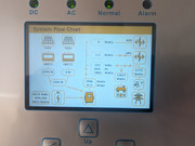
Then back to original position...
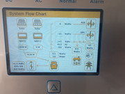
Then back to original position...
-
Countrypaul
- Posts: 637
- Joined: Sun Jul 18, 2021 11:50 am
Re: Solar PV advice
Ah, when you said house load went up I thought you were also measuring the house load seperately. The problem with just putting the CT in position 3 is that the inverter only measures the house load and then tries to get that to zero by sending more and more which gets exported rather than used. I guess tha is what Marcus was thinking when he commented about my first suggestion.
Re: Solar PV advice
Saw this video regarding the same problem. Interesting?
Re: Solar PV advice
Not looked at the vid (very slow copper wire broadband).
As there's little room to add a Henley between the existing Henley and the meter, can you instead add one to the right of the existing live henley (in the house c.u. tail), with enough room between the henleys to fit the ct clamp, then transfer the garage/pv tails to this new henley, leaving the e.v. charger on the original henley.
Depends on how comfortable you are playing with tails and henley blocks of course.
It should be fairly easy to extend the ct wires if necessary, although it can start to look a little untidy if there are lots of joins. And it's best to put the inverter onto standby whilst playing with the ct as it may do strange things whilst the ct isn't connected/attached to the tail.
450W hydro-electric
5110W pv
1.3kw Wt2 - not yet producing
6kWh lead acid - maybe 1kwh useable
LiMnCo battery made from 2nd hand hybrid car modules 3.6kwh nominal 24v.
300lt hot water tank and two storage heaters
ASHP Grant Aerona 3 10.5kw and UFH
5110W pv
1.3kw Wt2 - not yet producing
6kWh lead acid - maybe 1kwh useable
LiMnCo battery made from 2nd hand hybrid car modules 3.6kwh nominal 24v.
300lt hot water tank and two storage heaters
ASHP Grant Aerona 3 10.5kw and UFH
Re: Solar PV advice
Thanks Marcus.Marcus wrote: ↑Fri Apr 11, 2025 6:44 pm Not looked at the vid (very slow copper wire broadband).
As there's little room to add a Henley between the existing Henley and the meter, can you instead add one to the right of the existing live henley (in the house c.u. tail), with enough room between the henleys to fit the ct clamp, then transfer the garage/pv tails to this new henley, leaving the e.v. charger on the original henley.
Depends on how comfortable you are playing with tails and henley blocks of course.
It should be fairly easy to extend the ct wires if necessary, although it can start to look a little untidy if there are lots of joins. And it's best to put the inverter onto standby whilst playing with the ct as it may do strange things whilst the ct isn't connected/attached to the tail.
I would have to ask the installer to do the Henley blocks and tails I think. It's a bit too close to the mains for my liking and would be best to get the pro in!
The video basically says feed the EV live cable back through the inverter CT clamp.. it will deduct the power the EV is drawing from the total load the inverter CT clamp is reading. This will stop it calling for power from the battery to charge the EV. * That's what the video says and shows with a real life example *
Shame my CT clamp isn't wide enough to fit the EV live cable in though. I was thinking get another CT clamp and put it on the EV live cable and then wire up this new CT clamp to the inverter CT clamp. It has been extended with cat6 and a wago used to connect the CT clamps 2 wires to the cat6. So was thinking just connect them up like that?
Can two CT clamps be connected? God knows. Trying to keep it simple and DIY. I don't mind opening and closing a ct clamp!
Or buy a different (bigger) CT clamp. Unsure though if any brand ct clamp will work with this SunSynk inverter, or whether you have to use the original.
Re: Solar PV advice
I think two ct clamps can be used this way (although I'venot actuallytried it myself): ideally a matched pair, but ct clamps with an identical turns ratio ought to work (not sure what that would be for your inverter but a ratio of 2000:1 is common from memory) - or a ct clamp that can take both cables which has the turns ratio to suit the inverter.
If you have two ct clamps, you connect their output wires in parallel, and then the signal from the ev charger wire ct subtracts from the signal from the meter wire ct so the inverter does not 'see' the ev charger current coming from the grid.
If you have two ct clamps, you connect their output wires in parallel, and then the signal from the ev charger wire ct subtracts from the signal from the meter wire ct so the inverter does not 'see' the ev charger current coming from the grid.
450W hydro-electric
5110W pv
1.3kw Wt2 - not yet producing
6kWh lead acid - maybe 1kwh useable
LiMnCo battery made from 2nd hand hybrid car modules 3.6kwh nominal 24v.
300lt hot water tank and two storage heaters
ASHP Grant Aerona 3 10.5kw and UFH
5110W pv
1.3kw Wt2 - not yet producing
6kWh lead acid - maybe 1kwh useable
LiMnCo battery made from 2nd hand hybrid car modules 3.6kwh nominal 24v.
300lt hot water tank and two storage heaters
ASHP Grant Aerona 3 10.5kw and UFH