Page 1 of 1
How should I wire this panel?
Posted: Tue Jun 25, 2024 6:48 pm
by SafetyThird
Hi all, been a bit quiet of late, waiting for the sparky to come and move the inverters and batteries to their new home in the extension we've built.
Meanwhile, my wife has had a summer house built at the bottom of the field and we've just picked up a VTOMAN FlashSpeed 1500 Portable Power Station to give her power down there. It will take up to 400w of solar directly into the box as it has an in built MPPT controller with a minimum voltage of 30w.
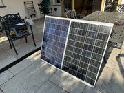
I have two 80w panels that have been sitting around for a while and I've just hinged them together and need to wire them in series to give the required voltage. Now, in the connector box there are two connectors each for +ve and -ve, with diodes in between. I'm connecting positive from the other panel to the negative terminal and then out again from the +ve, the negative lead from the other panel is joined in the box to the negative going out to the battery box. Here's a picture that I hope will make more sense of my description.
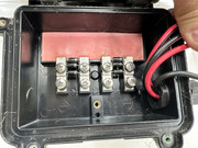
Question is, do I connect one or both of the positives on the diode input or output terminals?
Re: How should I wire this panel?
Posted: Tue Jun 25, 2024 8:50 pm
by Joeboy
SafetyThird wrote: ↑Tue Jun 25, 2024 6:48 pm
Hi all, been a bit quiet of late, waiting for the sparky to come and move the inverters and batteries to their new home in the extension we've built.
Meanwhile, my wife has had a summer house built at the bottom of the field and we've just picked up a VTOMAN FlashSpeed 1500 Portable Power Station to give her power down there. It will take up to 400w of solar directly into the box as it has an in built MPPT controller with a minimum voltage of 30w.
I have two 80w panels that have been sitting around for a while and I've just hinged them together and need to wire them in series to give the required voltage. Now, in the connector box there are two connectors each for +ve and -ve, with diodes in between. I'm connecting positive from the other panel to the negative terminal and then out again from the +ve, the negative lead from the other panel is joined in the box to the negative going out to the battery box. Here's a picture that I hope will make more sense of my description.
Question is, do I connect one or both of the positives on the diode input or output terminals?
Nothing in the manual I take it? I'd connect to the + diode input side but I'd be asking myself why the diode is needed. Is the battery at risk of backfeeding to panels?
Although.id also go against what I've just said and say the connection terminal.look to be bottom left negative and bottom right positive (after the diodes). I was of absolutely no help there! I don't like the look of the positive top left diode input side. It's a but close to the negative top right depending on size of end termination. Nope I'm going bottom left and bottom right terminals.
Re: How should I wire this panel?
Posted: Tue Jun 25, 2024 10:03 pm
by Marcus
I'd wire -ve wire to leftmost terminal only, and +ve to rightmost terminal only.
Those look like bypass diodes to me and the inner two terminals are intermediate connections to the cells: if you measure volts between the terminals with daylight on the panel i would expect the intermediate terminals would be either 1/3 & 2/3rds panel volts or both 1/2 panel volts (full voltage being between the two outer terminals).
Re: How should I wire this panel?
Posted: Tue Jun 25, 2024 10:14 pm
by ecogeorge
I'd put a meter across LH and RH connection. What voltage ??
George
Edit to add -as above post......
Re: How should I wire this panel?
Posted: Wed Jun 26, 2024 7:37 am
by SafetyThird
Thanks for the replies. Wasn’t sure if the diodes were just to prevent battery discharge or something else because of the two sets of terminals. I’ll put the meter on them today and report back.
Re: How should I wire this panel?
Posted: Wed Jun 26, 2024 6:10 pm
by SafetyThird
Ok, put the panels out in the sunshine and measured across the various connectors. Looking at the photo, numbered 1-4 left to right, voltages as follows:
1-2=10.5
1-3=10.5
1-4=20.8
2-3=0
2-4=10.2
3-4=10.2
Variance probably due to light level variation between readings.
So, connected the wires to 1 & 4 and getting 42v across the output. Perfect. Made up the Anderson connector, plugged into the power bank and even in the low evening sun with some shading the box was showing 40w going in. Will measure again tomorrow under full sun but looks like that's a winner.
Thanks for the help.
Re: How should I wire this panel?
Posted: Wed Jun 26, 2024 6:36 pm
by Joeboy
SafetyThird wrote: ↑Wed Jun 26, 2024 6:10 pm
Ok, put the panels out in the sunshine and measured across the various connectors. Looking at the photo, numbered 1-4 left to right, voltages as follows:
1-2=10.5
1-3=10.5
1-4=20.8
2-3=0
2-4=10.2
3-4=10.2
Variance probably due to light level variation between readings.
So, connected the wires to 1 & 4 and getting 42v across the output. Perfect. Made up the Anderson connector, plugged into the power bank and even in the low evening sun with some shading the box was showing 40w going in. Will measure again tomorrow under full sun but looks like that's a winner.
Thanks for the help.
This is turning into a great members day, woohoo!

