I dont post much but this PDF may be of some interest.
This is actuall Empirical Evidence after 23 years of RE operations.
AC COUPLING WITH OLD GTI’s
With a Main Inverter that takes a Battery DC voltage and changes it to a 120vac PSW 60HZ or a 230vac
50HZ, it’s the H BRIDGE design of the main Inverter that allows a two way flow.
Battery 48vdc creates 230vac Mini Grid. …….. GTI’s connected into this 230vac Mini Grid will push back and
raise its Ac voltage to just over the incoming voltage and push back through the Main Inverter Ac voltage
and the H BRIDGE design will convert this excess ac voltage to raw DC voltage which in turns feeds/charges
the battery. We call this process BACKCHARGING .
Used second hand GTI’s also have MPPT on the PV side, so power and voltage from the PV is maximised.
H BRIDGE, Simply put …… we have an oscillator that gets the toroid transformer switching on and off fast,
so creating a magnetically induced field in the windings.
Remember that the main Inverter needs to show these dumb GTI’s a clean Hz PSW, pure sine wave, and a
stable voltage supply.
With the OzInverter we keep the windings reasonably tight on the winding counts, so we have reasonable
headroom at about 44vdc to 62vdc of back charging the battery.
I have used 3 main methods to control the raw back charging by controlling the AC back charging GTI's. So
for the 'Warpverter', nothing would be much different.
In general we say that a 6Kw output main Inverter that can constantly give 6Kw, can normally take up to
about 11Kw of back charging from PV panels using GTI’s connected in to the Mini Grid that the Main
Inverter is creating.
Below is my published simple explanation on controlling that raw DC backcharging.
A very cost-effective solution for handling over 15kw of power from the PV panels arrays, etc, is to use
what is called 'AC Coupling'.
Houses that you see around the World with PV on the roofs will be using standard manufactured GTI's,
(Grid Tied Inverters) that take the PV DC output and change it to AC and feed it back at a few volts more
into the Mains Utilities Grid for that Country.
These GTI's are slave machines and need to see the correct AC voltage and the correct HZ frequency, so to
get their internal electronics/transformer to operate before they will feed into the Grid a few volts over
the Mains Utilities supplied voltage.
There are many Good Quality GTI's available second hand, i use fleebay etc, and i prefer GTI's with a toroid
transformer, see below photo of previously used SMA's........ . 150 to 300 Euros/$ each.
Our 48vdc ‘OzInverter’ H Bridge, creates a very stable 240vac or 120vac at a stable 50H or 60HZ, depends
on your country domestic voltage, and therefore allows 'AC Coupling'. The GTI's back charge through the
‘OzInverter’ to the battery bank any surplus power not being used on the OFF GRID or we call our
‘OzInverter’ created MINI GRID.
Three methods of controlling the raw back charging from GTI's is possible for 'AC Coupling'.
A. Use the Internal codes/settings in the GTI's to sequential shut down when a specified ac output voltage
is reached. This works reasonably well with my system as some installations GTI,s are up to 400 meters
away from the ‘OzInverter’ and batteries, and the batteries do push back slightly, but this depends on the
cable voltage sag.
B. Use dc voltage comparators circuit to shut down the GTI Ac side with a relay when the DC battery
voltage rises above a charging rate voltage. But you will need to run a data cable to all your installations,
and again allow for voltage sag.
C. Use PWM dc controllers that are connected directly to the 48vdc battery bank. These Diversion
controllers, (Morningstar Tristar PWM at about 200 Euros each), will regulate the charging and any excess
power when the batteries are full and will dump/divert to other permanently connected sources, ie, Air
Heaters 2kW each or Hot water heaters, underfloor electric heating, etc.
The above are a cost effective and very reliable system.
A is used most, and C is my guaranteed safety system. Where i do not have access to the GTI internals,
then i use B.
For a 19kW Array I prefer using 2off 1.7kW & 4off 2.5kW GTI's for 15kW, and using DC Charge controllers
for the 5kW as these can gently finish charging that precious 48vdc battery bank.
NOTE, I have not used a HF, High Frequency GTI, because second hand old heavy toroidal types are easily
obtainable and very cheap, plus you get to use the GTI internal MPPT . 'Oztules' and others have
experimented with HF types and do not find any real difficulties.
NOTE. Its best to use GTI’s at a max output of 2.5kW as above this, the GTI tends to surge on a long cable
connection and constantly triggering on and off on the bigger GTI's.
NOTE, So importantly the GTI’s output will always be used by your appliances etc, on the Mini grid you are
creating, and your battery bank will not really be used until the sun goes down, then the battery bank will
step in to use the main Inverter and run the appliances etc.
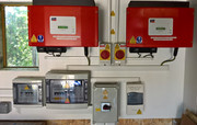
The two red boxes in the below photo are standard old MPPT GTI's that are used/second hand. There are also other installations on our 5 main buildings.
Each is rated at 1.8kW and capable of converting the ever-fluctuating sun shining PV DC voltage to 240vAC
to feed into our MINI GRID. This Garage roof PV install has 3.6kW max of PV and i have spilt them into 2 PV
strings of 1.8kW each so just about correct for each GTI.