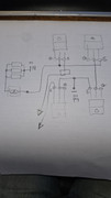
Ok, looking at that pic (and with the caveat that i don't know anything about how this inverter works - just guessing from the pic):
The original 8 fet h-bridge are under the pcb with the row of grey rectangular caps (in series with the transformer?), and the other pcb with the round d.c. battery caps for the h-bridge.
The high voltage side of the transformer goes to the four fets(?) In the middle. These are another h-bridge driver/rectifier. From there the power goes to/from the three big round 680uF caps - I'm guessing 400 - 600v?
I'm guessing this whole assembly is a bidirectional voltage conversion between battery d.c. and the three 680uF caps d.c. (but i could be wrong - it might convert one way (up) and the fets and other inductors are used to charge the battery (down)).
From there the four fets(?) On the right along with two of the three round torroids at the top-right are a bi-directional PWM h-bridge that produce /rectify the 50hz 230v sinewave a.c. (in sync with the grid when connected).
But the third round torroid inductor and the last pair of fets to the top-right - don't immediately present an obvoius explanation... could be a down converter to charge the battery, or a d.c. d.c. converter of other purpose.
Electronics help required with Sofar ME3000SP
Re: Electronics help required with Sofar ME3000SP
450W hydro-electric
5110W pv
1.3kw Wt2 - not yet producing
6kWh lead acid - maybe 1kwh useable
LiMnCo battery made from 2nd hand hybrid car modules 3.6kwh nominal 24v.
300lt hot water tank and two storage heaters
ASHP Grant Aerona 3 10.5kw and UFH
5110W pv
1.3kw Wt2 - not yet producing
6kWh lead acid - maybe 1kwh useable
LiMnCo battery made from 2nd hand hybrid car modules 3.6kwh nominal 24v.
300lt hot water tank and two storage heaters
ASHP Grant Aerona 3 10.5kw and UFH
Re: Electronics help required with Sofar ME3000SP
Yes. Grey caps are in series with the transformerMarcus wrote: ↑Mon Sep 11, 2023 7:01 pm Ok, looking at that pic (and with the caveat that i don't know anything about how this inverter works - just guessing from the pic):
The original 8 fet h-bridge are under the pcb with the row of grey rectangular caps (in series with the transformer?), and the other pcb with the round d.c. battery caps for the h-bridge.
Yes. It's difficult to see exactly where the output of this part is as it's in the middle layer of the PCB but I does look to be to the caps which are 450wv.
https://www.mouser.co.uk/datasheet/2/19 ... 163838.pdf
I've just removed these and measured the resistance between E and C and the all measure 0 ohms no matter which way round the probes are.
I'm not sure how it works. Everything to the DC side and from the DC side goes through the large transformer.
85no 58mm solar thermal tubes, 28.5Kw PV, 3x Sunny Island 5048, 2795 Ah (135kWh) (c20) Rolls batteries 48v, 8kWh Growatt storage, 22 x US3000C Pylontech, Sofar ME3000's, Brosley wood burner and 250lt DHW
Re: Electronics help required with Sofar ME3000SP
IGBTs - makes sense. That sounds like they're blown - Well i would use the diode test and you should get ~0.5v e -c and open cct the other way if the device is off, or about 1v if it's on. And the gate should read open circuit of course.Tinbum wrote: ↑Wed Sep 13, 2023 11:58 am Yes. It's difficult to see exactly where the output of this part is as it's in the middle layer of the PCB but I does look to be to the caps which are 450wv.
https://www.mouser.co.uk/datasheet/2/19 ... 163838.pdf
I've just removed these and measured the resistance between E and C and the all measure 0 ohms no matter which way round the probes are.
If the transformer is the only route from the battery side to the high voltage side then that would support the theory that the transformer can be driven either way: if discharging the battery you drive the transformer with the fets and use the body diodes of the igbts to rectify the output. If charging the battery, you would drive the transformer with the igbts and the battery side fets would rectify - but with the fets you might well use synchronous rectification to increase efficiency. There wouldn't be any point using synchronous rectification on the igbts.
I suppose you could try substitution of diodes for the igbts: it should then work battery to a.c. out.
Still not sure about the three torroidal inductors on the top right: each one seems to have a corresponding pair of fets(or igbts) but whilst having two as a h-bridge between 50hz a.c. and high voltage d c. Makes sense, I don't see what the 3rd one would do.
450W hydro-electric
5110W pv
1.3kw Wt2 - not yet producing
6kWh lead acid - maybe 1kwh useable
LiMnCo battery made from 2nd hand hybrid car modules 3.6kwh nominal 24v.
300lt hot water tank and two storage heaters
ASHP Grant Aerona 3 10.5kw and UFH
5110W pv
1.3kw Wt2 - not yet producing
6kWh lead acid - maybe 1kwh useable
LiMnCo battery made from 2nd hand hybrid car modules 3.6kwh nominal 24v.
300lt hot water tank and two storage heaters
ASHP Grant Aerona 3 10.5kw and UFH
Re: Electronics help required with Sofar ME3000SP
Diode mode reads 0v either way and gate reads 0 ohms to e or c.Marcus wrote: ↑Wed Sep 13, 2023 2:36 pm
IGBTs - makes sense. That sounds like they're blown - Well i would use the diode test and you should get ~0.5v e -c and open cct the other way if the device is off, or about 1v if it's on. And the gate should read open circuit of course.
I suppose you could try substitution of diodes for the igbts: it should then work battery to a.c. out.
I've ordered some replacements on the slow boat from china.
Thanks for the explanation and the help.Marcus wrote: ↑Wed Sep 13, 2023 2:36 pm If the transformer is the only route from the battery side to the high voltage side then that would support the theory that the transformer can be driven either way: if discharging the battery you drive the transformer with the fets and use the body diodes of the igbts to rectify the output. If charging the battery, you would drive the transformer with the igbts and the battery side fets would rectify - but with the fets you might well use synchronous rectification to increase efficiency. There wouldn't be any point using synchronous rectification on the igbts.
Still not sure about the three torroidal inductors on the top right: each one seems to have a corresponding pair of fets(or igbts) but whilst having two as a h-bridge between 50hz a.c. and high voltage d c. Makes sense, I don't see what the 3rd one would do.
I'll have a look and see if I can get an idea of how the torroidals are connected in.
85no 58mm solar thermal tubes, 28.5Kw PV, 3x Sunny Island 5048, 2795 Ah (135kWh) (c20) Rolls batteries 48v, 8kWh Growatt storage, 22 x US3000C Pylontech, Sofar ME3000's, Brosley wood burner and 250lt DHW
Re: Electronics help required with Sofar ME3000SP
Well, don't worry too much about the 3 torroids - we know there's a fault in the transformer drive circuits and the torroids may well be fine - whatever they do. It would be nice to know but might not be necessary.
Whilst waiting for parts i would be looking at the gate drive pulses on the igbts (if you can do so safely - as there's high voltage d.c. here and it's not isolated from the mains(probably), so neither +ve or -ve will be at safe "ground" voltage), or dead testing the gate drive components for the igbts.
Whilst waiting for parts i would be looking at the gate drive pulses on the igbts (if you can do so safely - as there's high voltage d.c. here and it's not isolated from the mains(probably), so neither +ve or -ve will be at safe "ground" voltage), or dead testing the gate drive components for the igbts.
450W hydro-electric
5110W pv
1.3kw Wt2 - not yet producing
6kWh lead acid - maybe 1kwh useable
LiMnCo battery made from 2nd hand hybrid car modules 3.6kwh nominal 24v.
300lt hot water tank and two storage heaters
ASHP Grant Aerona 3 10.5kw and UFH
5110W pv
1.3kw Wt2 - not yet producing
6kWh lead acid - maybe 1kwh useable
LiMnCo battery made from 2nd hand hybrid car modules 3.6kwh nominal 24v.
300lt hot water tank and two storage heaters
ASHP Grant Aerona 3 10.5kw and UFH
Re: Electronics help required with Sofar ME3000SP
Could the extra torrid be for the EPS. When the grid is down the inverter has an output that can supply mains to critical loads?
Great idea, I'll hopefully get chance over the weekend.
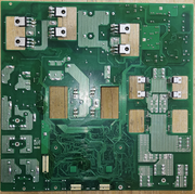
Edit rear of the Board.
Great idea, I'll hopefully get chance over the weekend.
Edit rear of the Board.
85no 58mm solar thermal tubes, 28.5Kw PV, 3x Sunny Island 5048, 2795 Ah (135kWh) (c20) Rolls batteries 48v, 8kWh Growatt storage, 22 x US3000C Pylontech, Sofar ME3000's, Brosley wood burner and 250lt DHW
Re: Electronics help required with Sofar ME3000SP
The IGBT's arrived yesterday so got them installed.
It seems to work but for some reason the enter buttons stopped working on the display. Swapped out the small wifi/ct/can/rs485 pcb with another good one and the enter button now works.
Another problem has occurred though. For some reason the CAN messages are going into fault and the battery is showing an error. This happens with either PCB. It's ok until the inverter starts to discharge the battery, I've not tried charging. This seems a little strange as I understood the batteries only send and dont receive messages, though the battery possibly has to receive an inverter pulse message. I do have another inverter on this battery with the CAN connected but this has always been ok when I've tested other inverters.
I don't want to damage the batteries so I'm going to set up a teensy to send fake battery CAN messages to the inverter and sniff them at the same time.
EdIt-found problem but not sure why. The battery pack I used has my Teensy CAN translator on it to the other inverter and it seemed to be some conflict with that.
85no 58mm solar thermal tubes, 28.5Kw PV, 3x Sunny Island 5048, 2795 Ah (135kWh) (c20) Rolls batteries 48v, 8kWh Growatt storage, 22 x US3000C Pylontech, Sofar ME3000's, Brosley wood burner and 250lt DHW
Re: Electronics help required with Sofar ME3000SP
So it's all working?  Or are you still testing?
450W hydro-electric
5110W pv
1.3kw Wt2 - not yet producing
6kWh lead acid - maybe 1kwh useable
LiMnCo battery made from 2nd hand hybrid car modules 3.6kwh nominal 24v.
300lt hot water tank and two storage heaters
ASHP Grant Aerona 3 10.5kw and UFH
5110W pv
1.3kw Wt2 - not yet producing
6kWh lead acid - maybe 1kwh useable
LiMnCo battery made from 2nd hand hybrid car modules 3.6kwh nominal 24v.
300lt hot water tank and two storage heaters
ASHP Grant Aerona 3 10.5kw and UFH
Re: Electronics help required with Sofar ME3000SP
It seems to be working ok but still really in the testing stage as without the enter button working I can't change any of the settings. I do have another pcb that I can use as a last resort but I'm trying other avenues first.
All the settings seem to be stored on the small pcb board that has the enter button fault. I can't even try reinstalling the firmware unless I can find the right file. It is possible to do it remotely but the firmware files I have only seem to be able to be suitable to be used on an SD card.
All the settings seem to be stored on the small pcb board that has the enter button fault. I can't even try reinstalling the firmware unless I can find the right file. It is possible to do it remotely but the firmware files I have only seem to be able to be suitable to be used on an SD card.
85no 58mm solar thermal tubes, 28.5Kw PV, 3x Sunny Island 5048, 2795 Ah (135kWh) (c20) Rolls batteries 48v, 8kWh Growatt storage, 22 x US3000C Pylontech, Sofar ME3000's, Brosley wood burner and 250lt DHW
Re: Electronics help required with Sofar ME3000SP
Do you have the Teensy CAN interface in passive mode?
Otherwise your battery will be seeing double ACKs for each message it sends.