LuxPower - emergency backup enabling

Lincs Robert
Posts: 214
Joined: Fri Mar 11, 2022 7:48 pm
Location: Lincolnshire

Re: LuxPower - emergency backup enabling

#11

Post by Lincs Robert »

nowty wrote: Sun Oct 16, 2022 3:52 pm
Lincs Robert wrote: Sun Oct 16, 2022 3:34 pm Thanks for the feedback - much appreciated.

Can anybody comment about the earthing arrangements when using the EPS output please. Does the Earth go “straight through”?

Thanks - Rob
Latest info here,
https://electrical.theiet.org/wiring-ma ... e-systems/
Thanks

So I’m assuming that the EPS supplied circuit(s) would be connected into the “new” Earth arrangement all the time. I’m thinking about a lighting circuit and some sockets. The lighting would then use the new Earth all the time as would anything fed from those sockets - I’m thinking broadband router etc.

Cheers
Swwils
Posts: 561
Joined: Sat Feb 26, 2022 12:58 pm

Re: LuxPower - emergency backup enabling

#12

Post by Swwils »

In island mode it will be TN-S. In connected mode it will depend on what your existing earthing arrangement is.

Depending on street connection, equipment, supplier etc your broadband may not work even if your router is powered.
Oldgreybeard
Posts: 1873
Joined: Thu Sep 09, 2021 3:42 pm
Location: North East Dorset

Re: LuxPower - emergency backup enabling

#13

Post by Oldgreybeard »

Swwils wrote: Sun Oct 16, 2022 5:43 pm In island mode it will be TN-S. In connected mode it will depend on what your existing earthing arrangement is.
Is that safe?

My understanding is that to ensure that the earthing system works when there's a power cut, which may well be a result of the distribution cable having been severed, then it's inherently unsafe to rely on any incoming earth (because it may well not exist).

To ensure there is an earthing system in the event of a power cut doesn't the whole installation need to either be TT, or switch to TT when the power fails?

I'm not sure I'd trust the TN-S incoming earth to always be there in the event of a fault that takes out the supply, especially as the TN-S earth conductor will most often be on the outside of the distribution cable, so the chances are that it will get severed before the line or neutral in the event of something like a digger accidentally cutting through a cable.
25 off 250W Perlight solar panels, installed 2014, with a 6kW PowerOne inverter, about 6,000kWh/year generated
6 off Pylontech US3000C batteries, with a Sofar ME3000SP inverter
Lincs Robert
Posts: 214
Joined: Fri Mar 11, 2022 7:48 pm
Location: Lincolnshire

Re: LuxPower - emergency backup enabling

#14

Post by Lincs Robert »

Oldgreybeard wrote: Sun Oct 16, 2022 5:59 pm
Swwils wrote: Sun Oct 16, 2022 5:43 pm In island mode it will be TN-S. In connected mode it will depend on what your existing earthing arrangement is.
Is that safe?

My understanding is that to ensure that the earthing system works when there's a power cut, which may well be a result of the distribution cable having been severed, then it's inherently unsafe to rely on any incoming earth (because it may well not exist).

To ensure there is an earthing system in the event of a power cut doesn't the whole installation need to either be TT, or switch to TT when the power fails?

I'm not sure I'd trust the TN-S incoming earth to always be there in the event of a fault that takes out the supply, especially as the TN-S earth conductor will most often be on the outside of the distribution cable, so the chances are that it will get severed before the line or neutral in the event of something like a digger accidentally cutting through a cable.
I was just thinking the same. Our supply comes in on an overhead cable - which seems to have 4 conductors. The supply to the house, a former pub, is 3 phase, but we only use one - the other two are capped off before our meter. I’m assuming that our Earth is neutral derived?
User avatar
nowty
Posts: 5886
Joined: Mon May 31, 2021 2:36 pm
Location: South Coast

Re: LuxPower - emergency backup enabling

#15

Post by nowty »

Lincs Robert wrote: Sun Oct 16, 2022 4:44 pm
nowty wrote: Sun Oct 16, 2022 3:52 pm
Lincs Robert wrote: Sun Oct 16, 2022 3:34 pm Thanks for the feedback - much appreciated.

Can anybody comment about the earthing arrangements when using the EPS output please. Does the Earth go “straight through”?

Thanks - Rob
Latest info here,
https://electrical.theiet.org/wiring-ma ... e-systems/
Thanks

So I’m assuming that the EPS supplied circuit(s) would be connected into the “new” Earth arrangement all the time. I’m thinking about a lighting circuit and some sockets. The lighting would then use the new Earth all the time as would anything fed from those sockets - I’m thinking broadband router etc.

Cheers
The general problem with these inverter “EPS” is you have to assume they are floating voltages. That is both neutral and live are effectively live voltages and not necessarily with respect to earth.

For using with double insulated non earthed "plugged in" appliances they should be safe and that's what they are really designed for. Most things like phone chargers, laptops, internet routers, most new TVs, some table lamps, etc.

But once you start connecting them to lighting circuits and plugging your fridge, toaster, etc into them they should have the right earthing system.
From,
https://electrical.theiet.org/wiring-ma ... e-systems/

"An installation that operates in island mode therefore requires:

• a switching mechanism to disconnect live conductors of the installation that are to be powered in island mode from the grid. The IET Code of Practice for Electrical Energy Storage Systems calls this an island mode isolator

• a switching mechanism to provide a neutral for the island mode The IET Code of Practice for Electrical Energy Storage Systems calls this an N-E bond relay, and

• a consumer earth electrode."


The first and maybe the second requirement might be performed by your inverter but there tends to be very little info in many of the badly interpreted Chinese manuals.
18.7kW PV > 109MWh generated
Ripple 6.6kW Wind + 4.5kW PV > 27MWh generated
6 Other RE Coop's
105kWh EV storage
60kWh Home battery storage
40kWh Thermal storage
GSHP + A2A HP's
Rain water use > 510 m3
sharpener
Posts: 435
Joined: Fri May 20, 2022 10:42 am

Re: LuxPower - emergency backup enabling

#16

Post by sharpener »

See also the long discussion in this thread viewtopic.php?f=14&t=1290&start=110
16 x 230W Upsolar panels S Devon, 4kW Steca, 3.9 MWh FITs/yr
8 x 405W Longi panels, 250/60 MPPT, 3.3 MWh/yr
Victron MultiPlus II-GX 48/5000/70-50
10.65 kWh Pylontec Force-L2
zappi 7kW EVCS
Villavent whole-house MVHR
5000l rainwater system
Vaillant 12kW HP
Swwils
Posts: 561
Joined: Sat Feb 26, 2022 12:58 pm

Re: LuxPower - emergency backup enabling

#17

Post by Swwils »

Oldgreybeard wrote: Sun Oct 16, 2022 5:59 pm
Swwils wrote: Sun Oct 16, 2022 5:43 pm In island mode it will be TN-S. In connected mode it will depend on what your existing earthing arrangement is.
Is that safe?

My understanding is that to ensure that the earthing system works when there's a power cut, which may well be a result of the distribution cable having been severed, then it's inherently unsafe to rely on any incoming earth (because it may well not exist).

To ensure there is an earthing system in the event of a power cut doesn't the whole installation need to either be TT, or switch to TT when the power fails?

I'm not sure I'd trust the TN-S incoming earth to always be there in the event of a fault that takes out the supply, especially as the TN-S earth conductor will most often be on the outside of the distribution cable, so the chances are that it will get severed before the line or neutral in the event of something like a digger accidentally cutting through a cable.
Its literally from the link:

https://electrical.theiet.org/wiring-ma ... e-systems/
In systems where a low voltage supply is provided to the installation, the neutral of the supply is earthed at the distributor’s transformer.

Accordingly, in systems operating in island mode, the distributor’s neutral-earth link cannot and must not be relied upon, as this is switched out when the live conductors are disconnected.

An installation that operates in island mode therefore requires:
  • a switching mechanism to disconnect live conductors of the installation that are to be powered in island mode from the grid. The IET Code of Practice for Electrical Energy Storage Systems calls this an island mode isolator
  • a switching mechanism to provide a neutral for the island mode The IET Code of Practice for Electrical Energy Storage Systems calls this an N-E bond relay, and
  • a consumer earth electrode. In TT systems, this may be the TT system consumer electrode, if it meets specific technical requirements.
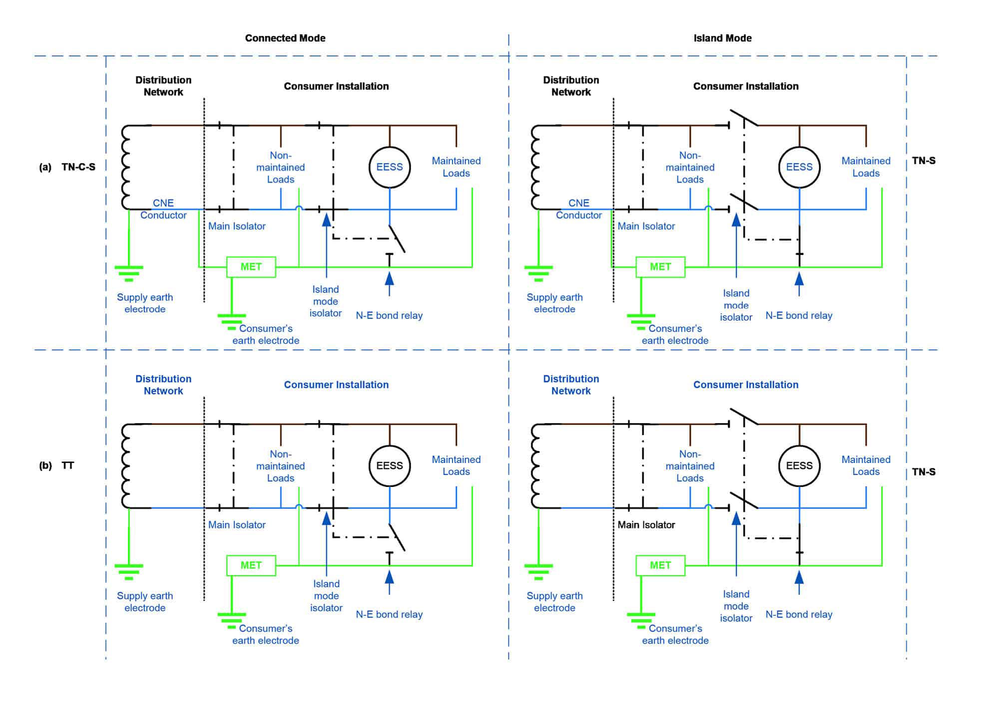
The earthing arrangement of most EESS in island mode, where the installation has a low voltage public supply connection, is therefore always TN-S.
Simplified illustration of earthing and switch-over arrangements in connected mode and island mode

Image
Oldgreybeard
Posts: 1873
Joined: Thu Sep 09, 2021 3:42 pm
Location: North East Dorset

Re: LuxPower - emergency backup enabling

#18

Post by Oldgreybeard »

All of those diagrams show the islanded supply as TT, in effect, though (they all have a local earth electrode providing earthing). There doesn't seem to be a diagram for TN-S, may be that got clipped out from the right of the image?

The three (non-island mode) normal UK earthing systems are:

TN-C-S/PME: earthing provided via the neutral conductor coming into the installation, where the MET is connected to the supply neutral, as shown in this illustration from the IET On-Site Guide (OSG):
TN-C-S.jpg
TN-C-S.jpg (35.51 KiB) Viewed 1744 times
TN-S: earthing provided via a separate (hence the "S") cable sheath earth conductor that comes in with the main supply cable and is connected to the MET, as shown in this illustration from the OSG:
TN-S.jpg
TN-S.jpg (28.03 KiB) Viewed 1744 times
TT: earthing is provided via a local earth electrode provided via the consumer that is connected to the MET, as shown in this illustration from the OSG:
TT.jpg
TT.jpg (37.71 KiB) Viewed 1744 times

In every case whenever there is a local earth electrode providing earthing the installation is effectively TT when in that configuration, in that any earth fault current is going to flow via the local earth electrode when in EPS mode.
25 off 250W Perlight solar panels, installed 2014, with a 6kW PowerOne inverter, about 6,000kWh/year generated
6 off Pylontech US3000C batteries, with a Sofar ME3000SP inverter
Swwils
Posts: 561
Joined: Sat Feb 26, 2022 12:58 pm

Re: LuxPower - emergency backup enabling

#19

Post by Swwils »

Note the source of supply in the island mode and the earthing arrangement in that mode. It's TN-S. Please read the link.
Oldgreybeard
Posts: 1873
Joined: Thu Sep 09, 2021 3:42 pm
Location: North East Dorset

Re: LuxPower - emergency backup enabling

#20

Post by Oldgreybeard »

Swwils wrote: Mon Oct 17, 2022 9:44 am Note the source of supply in the island mode and the earthing arrangement in that mode. It's TN-S. Please read the link.
Strictly speaking this is NOT TN-S, at least as far as the earth fault current path is concerned, which is all the matters.

With TN-S the earth fault current path is only via the distributor provided earth conductor, usually the cable sheath, that runs directly back to the local transformer earth. There is NO other earth fault current path with TN-S.

With TT, the earth fault current path is local, via the local earth electrode.

What the IET are suggesting is a hybrid earthing system whereby an additional TN-C-S/PME intermediate earth is provided at the consumer end. With TN-S there is NO earth electrode at the consumer end, the earthing system relies 100% on the integrity of the separate earth conductor provided by the distributor.

Whatever the hybrid system suggested is, it is definitely not TN-S (see the diagrams I posted from the OSG). Going right back to basics, The form of the abbreviation runs from the generator (left) to the consumer (right), so TN-S means Terra (earth) at the generator end, Neutral and earth are Separate, which means that the earth conductor is separate from all other conductors and there are no additional earth electrodes anywhere other than at the generator end (usually the distribution transformer). There is no local earth electrode at the consumer end with TN-S, if there was then there would need to be another T (for Terra, earth) at the right hand end of the abbreviation (as there is with TT).

My understanding is that the recommendation at the moment is to add an additional consumer earth electrode IF the supply is TN-C-S/PME. This adds a local intermediate earth that can provide an earth fault current path in the event that the distributor's earth is broken. This still falls within the TN-C-S/PME definition, as that earthing system uses several intermediate earth electrodes along the distribution route for redundancy (hence the word "Multiple" in PME) and a degree of fault tolerance. The regs changed a year or so ago to allow the use of a consumer intermediate earth electrode with TN-C-S, presumably as a precursor to more homes having a backup capable battery system.

This makes the supply TT at the consumer end when in island mode. The first T is the earth at the generator end, the second T is the consumers earth electrode that is added to provide a fault current path to earth locally.
25 off 250W Perlight solar panels, installed 2014, with a 6kW PowerOne inverter, about 6,000kWh/year generated
6 off Pylontech US3000C batteries, with a Sofar ME3000SP inverter
Post Reply