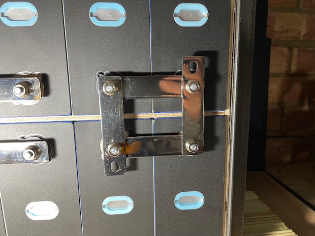
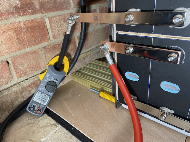
Nowty Towers DIY Battery Project

User avatar
nowty
Posts: 6293
Joined: Mon May 31, 2021 2:36 pm
Location: South Coast

Re: Nowty Towers DIY Battery Project

#31

Post by nowty »

Back to the new battery bank with yesterdays tensioning of the springs. :O:

Most modern LFP prismatic cell datasheets have a spec for optimum cycle life of a preload compression force of 300kg at a cell SOC of between 10% and 40%.

I have used these springs which are extra heavy duty 64mm long from here,
https://www.cromwell.co.uk/shop/fastene ... s/c/231108

The spec of the springs is a Rigidity of 41.2 Nmm which I am interpreting as a compression force of 41.2 N/mm or 4.2 kg / mm, so does that mean a compression of 71 mm for 300kg ?

I also have a spring at each end so is that equivalent as a fixed end and a longer spring at the other end with double the compression ?

Also I have 4 per each end ?, does that make a difference ?

My head hurt so I decided to do an experiment by clamping my weighing scales between the compression plates and winding up the springs until I had equal length compression on all springs AND the scale showed the max capacity of the scales at 150kg.
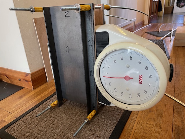
Image


I then measured the compression of the springs which was 64mm - 55mm = 9mm. This suggests I need 18mm of compression to achieve 300kg which would mean compressing the springs down to 46mm.
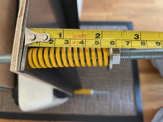
Image


The new cells arrived with a voltage of 3.29V which is around 50% SOC so I discharged them a bit to get them to 3.26V which is just under 40% SOC. I left the cell bus bars loose and cranked up the springs which was quite difficult because of access and the rods kept turning with the nuts so I had to hold the threaded bar with pipe wrenches whilst I turned the nuts. It took ages and I occasionally rocked the whole battery bank which was quite easy as they are sitting on a narrower deck board, steadied with the angle iron feet. This allowed the feet to move slightly and aided settlement of the two decks of cells.


Once I got down to 52mm (i.e. 12mm compression) the angle irons started to bend slightly, only about 1mm from midpoint to top or bottom but its the limit of my design. :facepalm:
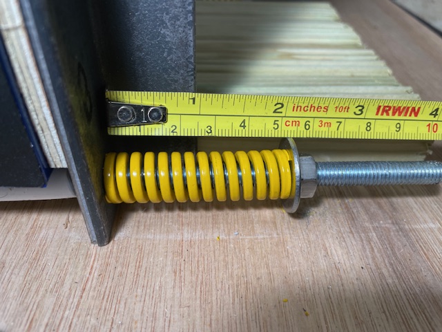
Image

So I make that about 200kg of preload force on the cells which although is not quite the 300kg spec, its a lot better than zero. :xx:
I reckon if you want the full 300kg preload force, its going to need 5mm steel plate and 5mm thick angle iron. Mine is 3mm and thats heavy enough. :shock:
If a 16 cell battery was made on a single deck with shorter angle irons, 3mm would probably still get you to 300kg without bending.
18.7kW PV > 110MWh generated
Ripple 6.6kW Wind + 4.5kW PV > 33MWh generated
7 Other RE Coop's
105kWh EV storage
90kWh Home battery storage
40kWh Thermal storage
GSHP + A2A HP's
Rain water use > 530 m3
Marcus
Posts: 304
Joined: Mon Nov 08, 2021 6:25 pm

Re: Nowty Towers DIY Battery Project

#32

Post by Marcus »

Sorry if this is a silly question, but I thought the cells were supposed to be clamped rididly so they couldn't expand at all?

ie if preloaded to 300kg, and the internal pressure went up due to working the cells, the clamp pressure would go up as the cells couldn't expand. Whereas, if you use springs, you get a constant preload, but then when the cells internal pressure rises they can expand against the springs whilst the preload remains aroung 300kg?
450W hydro-electric
5110W pv
1.3kw Wt2 - not yet producing
6kWh lead acid - maybe 1kwh useable
LiMnCo battery made from 2nd hand hybrid car modules 3.6kwh nominal 24v.
300lt hot water tank and two storage heaters
ASHP Grant Aerona 3 10.5kw and UFH
User avatar
nowty
Posts: 6293
Joined: Mon May 31, 2021 2:36 pm
Location: South Coast

Re: Nowty Towers DIY Battery Project

#33

Post by nowty »

Marcus wrote: Fri Mar 14, 2025 7:40 pm Sorry if this is a silly question, but I thought the cells were supposed to be clamped rididly so they couldn't expand at all?

ie if preloaded to 300kg, and the internal pressure went up due to working the cells, the clamp pressure would go up as the cells couldn't expand. Whereas, if you use springs, you get a constant preload, but then when the cells internal pressure rises they can expand against the springs whilst the preload remains aroung 300kg?
They will expand, there is no way of stopping the process, but better for them to expand within the cell or in the longer two axis than the shorter direction you add the preload force to. I believe thats the reasoning behind it.

What you are saying is probably the best way but how do you know how much pressure your applying, if any ?

If you put them say into a standard off the shelf case, there is no preload force at all, maybe a packer and a bit of foam, the cells will expand into the available space available. I ran them up last night to my cut off voltage of 55.68V (average of 3.48V a cell which is about 99% SOC) and the springs did not even move 1mm.
18.7kW PV > 110MWh generated
Ripple 6.6kW Wind + 4.5kW PV > 33MWh generated
7 Other RE Coop's
105kWh EV storage
90kWh Home battery storage
40kWh Thermal storage
GSHP + A2A HP's
Rain water use > 530 m3
Marcus
Posts: 304
Joined: Mon Nov 08, 2021 6:25 pm

Re: Nowty Towers DIY Battery Project

#34

Post by Marcus »

Ok, I think I understand:
With the recommended 300kg preload, the internal pressure should never exceed that, so not cause the cells to expand against the springs.

Whereas if you put them in a standard rigid case without preload, they will expand at some point until any residual wiggle room has been used up.

And that the former is preferred option for maximum cycle life.

I suppose another way might be to use a set of scales like you did, and work out what torque is needed on the nuts to achieve the 300kg, then torque up the rods without the springs.
450W hydro-electric
5110W pv
1.3kw Wt2 - not yet producing
6kWh lead acid - maybe 1kwh useable
LiMnCo battery made from 2nd hand hybrid car modules 3.6kwh nominal 24v.
300lt hot water tank and two storage heaters
ASHP Grant Aerona 3 10.5kw and UFH
User avatar
nowty
Posts: 6293
Joined: Mon May 31, 2021 2:36 pm
Location: South Coast

Re: Nowty Towers DIY Battery Project

#35

Post by nowty »

Marcus wrote: Fri Mar 14, 2025 9:34 pm I suppose another way might be to use a set of scales like you did, and work out what torque is needed on the nuts to achieve the 300kg, then torque up the rods without the springs.
I did read somewhere someone worked out how much torque on a nut to achieve the 300kg force but it probably depends on the size of nut, how stiff or lubricated it is etc, etc.

But its not the end of the world even if you don't put any preload force, they should still last a couple of thousand cycles or so. I just don't want to have to replace them for as long as possible as their location is difficult to install or remove them. In contrast my LMC cells are discrete metal cells which are already strongly contained in a cylinder. Thats one of the reasons Tesla use them even if at first you think it must be nuts to power a car out of thousands of single cells. Mechanical strength, good thermal properties for thermal management and plenty of redundancy if one or two age out.
18.7kW PV > 110MWh generated
Ripple 6.6kW Wind + 4.5kW PV > 33MWh generated
7 Other RE Coop's
105kWh EV storage
90kWh Home battery storage
40kWh Thermal storage
GSHP + A2A HP's
Rain water use > 530 m3
User avatar
nowty
Posts: 6293
Joined: Mon May 31, 2021 2:36 pm
Location: South Coast

Re: Nowty Towers DIY Battery Project

#36

Post by nowty »

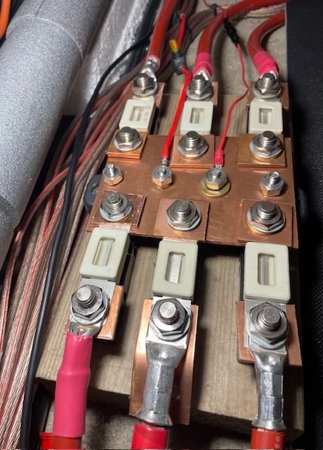
I've added my final fuse to my main positive terminal for use with this battery bank, it now has 4 battery banks and 2 battery inverter / charge controller sources. :twisted:
Image

New battery bank undergoing trials and as expected it seems to have added about a third more capacity battery to Nowty Towers. The charge up and is now taking too long so I'll have to add another ME3000SP for extra charging capacity. :mrgreen:

First run I charged it at a max of just under 0.2C, around 100A, the new battery bank bus bars are only tensioned a little over hand tight for now in case of settling in movement. Even at 100A I could not feel any heat on the cell bus bars and no change in the spring compression length so far.

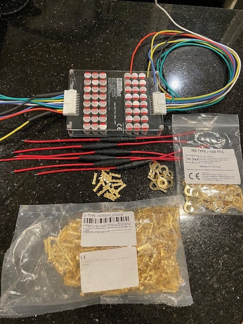
After a few more cycles I will tighten up the cell bus bars and add an active cell balancer which is work in progress.
Image


Links to the battery balancer stuff from the Ali'Express,
https://www.aliexpress.com/item/4000938109615.html 16S Active cell balancer.

https://www.aliexpress.com/item/1005004778084561.html Acrylic protective cover for cell balancer.

https://www.aliexpress.com/item/1005007078035872.html Optional fused links.

https://www.aliexpress.com/item/1005001947577525.html Crimp wire joiners.

https://www.aliexpress.com/item/1005003732275264.html M6 Ring crimp lugs.
18.7kW PV > 110MWh generated
Ripple 6.6kW Wind + 4.5kW PV > 33MWh generated
7 Other RE Coop's
105kWh EV storage
90kWh Home battery storage
40kWh Thermal storage
GSHP + A2A HP's
Rain water use > 530 m3
AGT
Posts: 1152
Joined: Sat Jan 29, 2022 11:26 am

Re: Nowty Towers DIY Battery Project

#37

Post by AGT »

nowty wrote: Wed Mar 12, 2025 8:31 pm The 1 hour saving session went in a blink of an eye whilst I was moving batteries into the battery cave by torchlight. :xx:

But I'm now in pain, cell tensioning will have to wait till tomorrow. :facepalm:

No pain, no gain. :twisted:
Image


Would it please be possible to give some futher info on the cell layout ie positive and negative and the bus bar layout, likewise how you balanced the cells before figuring out their position in the bank.

Thanks!
User avatar
nowty
Posts: 6293
Joined: Mon May 31, 2021 2:36 pm
Location: South Coast

Re: Nowty Towers DIY Battery Project

#38

Post by nowty »

AGT wrote: Sat Mar 15, 2025 1:40 pm
Would it please be possible to give some futher info on the cell layout ie positive and negative and the bus bar layout, likewise how you balanced the cells before figuring out their position in the bank.

Thanks!
I did not need to balance the cells, they came with very close voltages to not need to do so, I monitored the cell voltages with a multimeter as the bank reached my cut off voltage of 55.68V (average cell voltage 3.48V), the highest cell voltage reached just over 3.5V so was comfortably below the 3.65V max cut off spec for LFP cells. Thereafter that makes me confident to run the bank without fitting the cell balancer for a few days. I used to run two of my existing banks without a balancer for around 2 years before they drifted out enough to need one.

I had already explained how I matched up the cell pairs back here, it does not matter their actual position in the bank.
https://camelot-forum.co.uk/phpBB3/view ... =10#p57332

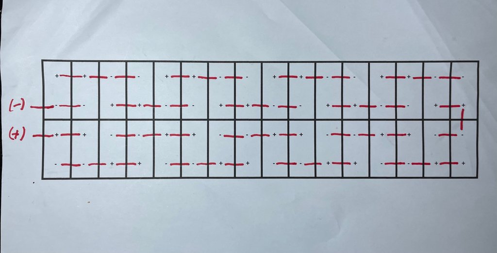
The cell orientation and therefore the bus bar layout is the ONLY thing I have actually written down as I needed to be sure I did not feck it up, or else the day won't end well. :?
Image


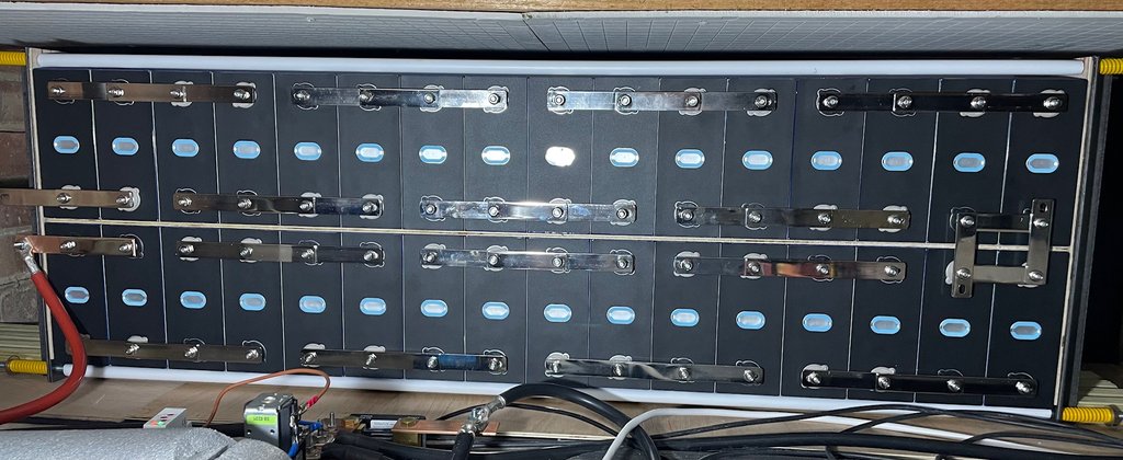
Compare that to the actual bank, the black terminals are positive and the cream colour is negative, I did check every cell with a multimeter in case any had been mismarked. I have used 4 cell wide bus bars to make my life easier.
Image


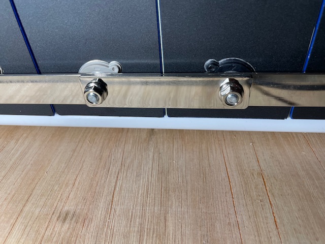
As I had a load of the single cell bus bars left over I have used them to double up the busbar connecting up each parallel pair where the current doubles. Its quite difficult to see in the photo. The busbars are 20mm wide and 2mm thick nickel plated copper, so are equivalent to 40mm2 and 80mm2 on the double up. My leads back to my main bus bars are 50mm2.
Image


Finally, the bus bar connections between the upper and lower decks had to be custom drilled because the spacing difference. I used a slightly different layout here from my hand written mark up. This is because I could not fit 3 busbars on a single terminal post.
Image
Last edited by nowty on Sat Mar 15, 2025 6:36 pm, edited 1 time in total.
18.7kW PV > 110MWh generated
Ripple 6.6kW Wind + 4.5kW PV > 33MWh generated
7 Other RE Coop's
105kWh EV storage
90kWh Home battery storage
40kWh Thermal storage
GSHP + A2A HP's
Rain water use > 530 m3
User avatar
Stinsy
Posts: 3486
Joined: Wed Jun 02, 2021 1:09 pm

Re: Nowty Towers DIY Battery Project

#39

Post by Stinsy »

I’ve seen 3D printed terminal/busbar covers. Are you planning to do something along those lines? I’d be terrified of an accidental short…
12x 340W JA Solar panels (4.08kWp)
3x 380W JA Solar panels (1.14kWp)
6x 2.4kWh Pylontech batteries (14.4kWh)
LuxPower inverter/charger

(Artist formally known as ******, well it should be obvious enough to those for whom such things are important.)
User avatar
nowty
Posts: 6293
Joined: Mon May 31, 2021 2:36 pm
Location: South Coast

Re: Nowty Towers DIY Battery Project

#40

Post by nowty »

Stinsy wrote: Sat Mar 15, 2025 3:42 pm I’ve seen 3D printed terminal/busbar covers. Are you planning to do something along those lines? I’d be terrified of an accidental short…
Generally no, its in an inaccessible place, but I will be protecting the power take off points, they really scare me if the upper terminal post was to fail and the upper bus bar was to slide down. But probably no drama as the forklift fuse would blow.
Image
18.7kW PV > 110MWh generated
Ripple 6.6kW Wind + 4.5kW PV > 33MWh generated
7 Other RE Coop's
105kWh EV storage
90kWh Home battery storage
40kWh Thermal storage
GSHP + A2A HP's
Rain water use > 530 m3
Post Reply