ALAN/ALAN D wrote: ↑Fri Mar 10, 2023 9:49 am
Is there an Earth connection on your
Generation Meter. Utility Meter and Energy Meter. ?
There is an earth in the generation meter, but I'm pretty certain its just looped into a terminal block, when the E112 was fitted an earth was taken from this terminal block to the earth terminal in the metal housing that the E112 is installed in, I've altered the drawing to reflect this.
No, the utility meter doesn't have an earth, I'd checked a photo of it when I did the drawing and it looked like an earth went in to it, but it actually runs up the side, do I've deleted that, thanks.
sharpener wrote: ↑Fri Mar 10, 2023 3:55 pm
If they were being picky they might want to see an RCD protecting the Quattro, not a fused switch, as mandated by the IET CoP.
Otherwise it looks a very neat and comprehensive job to judge by yr pix in the other thread.
Thanks, for whatever reason the electricians didn't install one, but if the DNO are picky then I can get one fitted.
Countrypaul wrote: ↑Fri Mar 10, 2023 5:02 pm
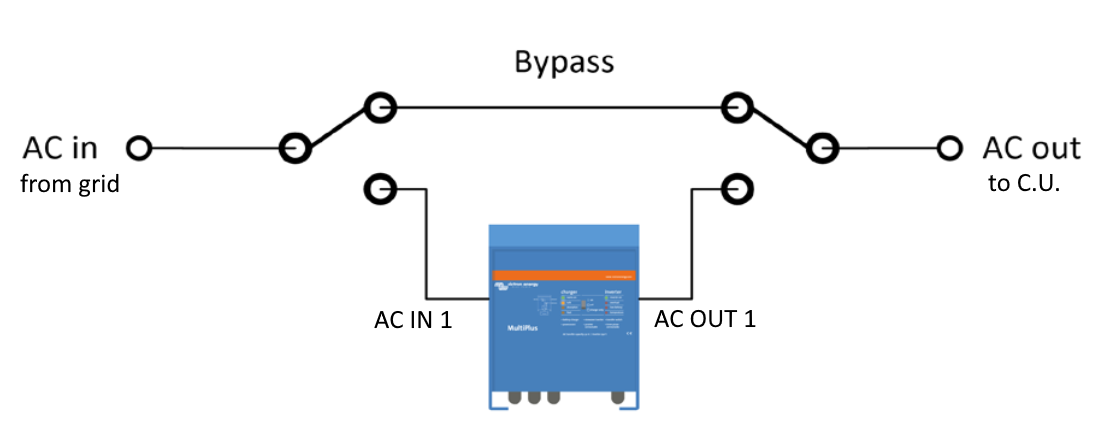
Looking at your emergency Inverter bypass and the two three position changeover switches it would appear that you could connect the output from the Quattro to the grid, which if that output is not grid tied would be a problem. There are no notes on the sketch to explain which connection on the quattro is being used in that part of the sketch.
Thanks, I'll update the drawing to show which connections are being used. My understanding is that there is no possibility of feeding the grid from AC Out 1, the electricians who installed the AC side of the install checked it, and were happy with it. Perhaps I'll also change that part of the drawing to make it clearer.
Can you not use 1 changeover switch.
If you flip your switch around so
The electricians did ponder that, but you then back feed AC OUT 1, so still need an isolator switch for that, but we came to the conclusion two change over switches was better. That drawing actually came from Victron, possibly the wiring unlimited book.
The one in the wiring diagram is based on one switch that does it all. I have a single wire going into the Quattro with an isolator. Then the output goes into a relay which chooses the grid or ac out to feed the consumer unit. You cannot back feed as the consumer unit has no other paths to grid.
Could the change over switch be changed to Keep the not Quite normal people Happy.
The one in your drawing could not operate between polls because the line is to Long to allow the switch contact To Move.
Will I get a Life one Day. ?
Andy wrote: ↑Sat Mar 11, 2023 11:10 pm
The one in the wiring diagram is based on one switch that does it all. I have a single wire going into the Quattro with an isolator. Then the output goes into a relay which chooses the grid or ac out to feed the consumer unit. You cannot back feed as the consumer unit has no other paths to grid.
Yes I think that is the more usual configuration. Lockable 2-pole RCBO is more compact and cheaper than a changeover switch.
Wish I had thought of using a contactor though, will change it in slow time, it will avoid the risk of the inverter failing while I am away and the freezer then being turned off.
Is that why you did it? Presumably the coil is fed from the AC Out?
16 x 230W Upsolar panels in S Devon, ~3.9 MWh/year
8 x 405W Longi panels, 3.355 MWh/yr projected
Victron MultiPlus II-GX 48/5000/70-50 with 250/60 MPPT
3 x Pylontec 3.55 kWh Force-L2
zappi 7kW EV charger
Villavent whole-house MVHR
5000l rainwater system
It’s a nice picture but all the DC charge controller stuff is not relevant to the DNO. Your, adding an AC coupled energy storage device to an existing AC coupled PV system, end of, keep it simple.
Do you really want to show off the EPS side of things to the DNO ?, your potentially opening up a can of worms with respect to live + neutral grid disconnection (island mode isolator), live and neutral reconnection on the off grid side (N-E bond relay) and the earthing arrangement. More info may be requested.
nowty wrote: ↑Sun Mar 12, 2023 5:08 pm
It’s a nice picture but all the DC charge controller stuff is not relevant to the DNO. Your, adding an AC coupled energy storage device to an existing AC coupled PV system, end of, keep it simple.
Do you really want to show off the EPS side of things to the DNO ?, your potentially opening up a can of worms with respect to live + neutral grid disconnection (island mode isolator), live and neutral reconnection on the off grid side (N-E bond relay) and the earthing arrangement. More info may be requested.
I was beginning to wonder whether, although it is excellent for home and future sparky reference, it might be more than was needed for the authorities...
Like dealing with an auditor: never tell them anything, other than just answering their questions!
2.0 kW/4.62 MWhr pa in Ripples, 4.5 kWp W-facing pv, 9.5 kWhr batt
30 solar thermal tubes, 2MWhr pa in Stockport, plus Congleton and Kinlochbervie Hydros,
Most travel by bike, walking or bus/train. Veg, fruit - and Bees!
Andy wrote: ↑Sat Mar 11, 2023 11:10 pm
The one in the wiring diagram is based on one switch that does it all. I have a single wire going into the Quattro with an isolator. Then the output goes into a relay which chooses the grid or ac out to feed the consumer unit. You cannot back feed as the consumer unit has no other paths to grid.
Yes I think that is the more usual configuration. Lockable 2-pole RCBO is more compact and cheaper than a changeover switch.
Wish I had thought of using a contactor though, will change it in slow time, it will avoid the risk of the inverter failing while I am away and the freezer then being turned off.
Is that why you did it? Presumably the coil is fed from the AC Out?
It’s a manual changeover. Sorry wrong terminology. But now you mention it …..
The manual changeover switches take up four DIN modules. In the same space you could get this changeover contactor from MCS and a 6A mcb to protect the coil and serve as a manual control.
16 x 230W Upsolar panels in S Devon, ~3.9 MWh/year
8 x 405W Longi panels, 3.355 MWh/yr projected
Victron MultiPlus II-GX 48/5000/70-50 with 250/60 MPPT
3 x Pylontec 3.55 kWh Force-L2
zappi 7kW EV charger
Villavent whole-house MVHR
5000l rainwater system