I used a new modern digital voltage meter and a trusty old digital meter to test the input voltage by placing the probes directly into the Immersuns live input voltage feed (the green terminal block) which I thought would be good enough to measure the input voltage and compare that to what the Immersun thought it was.
I checked the Immersun as thoroughly as I could for any dry joints or bad traces and looked for any damaged components - They all looked fine to me. The electric cabling going from the Immersun to the Immersion heaters are new and so are the heating elements and thermostats (top and bottom) I recently tightened all the screws within the green junction boxes which connect the electric wiring to the Immersuns PCB connections. They weren’t loose to start with though and the connector blocks on the PCB area soldered tight and there’s no sign of arcing.
The original Varistors and Triac were intact and didn’t show any evidence of failure or damage or scorching. I only replaced one of the Varistors (TMOV20RP175M) and Triac (BTA41-800B) on the advice of a fellow enthusiast (the person with the YouTube video showing a blown to pieces Varistor) He said it was worth taking a chance for a few quid to see if it resolved the error 8 - short circuit. Unfortunately that didn’t resolve that error until I replaced the T1 transformer which did but in doing so I then created a new error 10 - over voltage, which may be by pure coincidence.
In answer to your question about the Varistors, when I was checking the board closely I noticed a second Varistor (S14K275 VARISTOR 387V 4.5KA DISC 14MM) and that’s when I decided to replace that one too. I made absolutely sure all the components were replaced like for like and the soldering was perfect (been doing lots of practice). I know it’s not a perfect answer but I checked the capacitors visually and they appeared to be okay, they didn’t shown any classic signs of being blown or misshapen.
If it helps I could take a few pictures of the Immersun PCB with the LCD daughterboard removed to try and identify the version of the Immersun and various components used.
immersun repair -no.3
Re: immersun repair -no.3
Ok, so you're reading input voltage at the immersun (good) but if the voltage is spiking up to 260v then a digital meter might not capture it - hence the thought of using a lamp as you'd see it brighten momentary.
Sounds like there was no issue with the varistors so no evidence of large voltage spiked on the board - so no reason to suspect the 5uF capacitors.
I'm assuming that T1 is the current sense transformer as it causes the short cct error? I've not encountered that fault so i don't know. I don't see how replacing it could cause the overvoltage error, so I'm assuming it is a coincidence that this new error has occurred now - but, if we consider the possibility that it is connected:-
As the current sense transformer signal output and the output side of the grid voltage sense opto-isolator are both connecting to the 5v supplied logic inputs it might be possible for a fault on one to influence the other (although I'm guessing the new T1 is working as it should?). Without casting aspersions on your work i would double check there are no stray solder blobs or the like, then trace the signal from T1 back to the opamp/comparator i.c. that processes its signal, and trace the grid voltage input cct on both sides of the opto-isolator - just to be sure that all the joints & components are sound.
Trouble with a fault like this is that you can end up clutching at straws - sometimes it's easier to wait until it's developed a bit more.
450W hydro-electric
5110W pv
1.3kw Wt2 - not yet producing
6kWh lead acid - maybe 1kwh useable
LiMnCo battery made from 2nd hand hybrid car modules 3.6kwh nominal 24v.
300lt hot water tank and two storage heaters
ASHP Grant Aerona 3 10.5kw and UFH
5110W pv
1.3kw Wt2 - not yet producing
6kWh lead acid - maybe 1kwh useable
LiMnCo battery made from 2nd hand hybrid car modules 3.6kwh nominal 24v.
300lt hot water tank and two storage heaters
ASHP Grant Aerona 3 10.5kw and UFH
Re: immersun repair -no.3
I would agree entirely. It’s not easy to identify the exact fault at the moment and I don’t have an in-depth knowledge of electronics, although I’m keen to learn. Im quite happy to leave it as it is and report back if anything changes.
By the way I purchased two T1 transformers as they were only €8 each. When the error 10 first appeared I removed the newly fitted transformer and replaced it with the second new transformer as I thought it might have been faulty. Unfortunately that didn’t make any difference to the error. The description of the part was VOLTAGE MEASUREMENT TRANSFORMER 6100-SVL101201
I would like to thank you for all your help and advice.
Re: immersun repair -no.3
No worries; that appears to be a voltage sensing transformer - which is a surprise to me as i don't see what that has to do with the original short circuit error - although it does seem to have cured that.
If i get time I'll have a look at the immersun I've got here - I've not actually looked into those parts of the immersun so i may be making false assumptions about what's going on.
If i get time I'll have a look at the immersun I've got here - I've not actually looked into those parts of the immersun so i may be making false assumptions about what's going on.
450W hydro-electric
5110W pv
1.3kw Wt2 - not yet producing
6kWh lead acid - maybe 1kwh useable
LiMnCo battery made from 2nd hand hybrid car modules 3.6kwh nominal 24v.
300lt hot water tank and two storage heaters
ASHP Grant Aerona 3 10.5kw and UFH
5110W pv
1.3kw Wt2 - not yet producing
6kWh lead acid - maybe 1kwh useable
LiMnCo battery made from 2nd hand hybrid car modules 3.6kwh nominal 24v.
300lt hot water tank and two storage heaters
ASHP Grant Aerona 3 10.5kw and UFH
Re: immersun repair -no.3
If you do get chance to look at your Immersun that would be fantastic and greatly appreciated.
-
ALAN/ALAN D
Re: immersun repair -no.3
Various radio club members that have worked at Plessey, Marconi on design / repair of military equipment all agree that the printed circuit board on that model of the Immersun diverter is not fit for purpose. 
No consideration has been given into the component track position in relation to normal design current flow or high current component failure.
No consideration has been given into the component track position in relation to normal design current flow or high current component failure.
Re: immersun repair -no.3
!
Thats where experience comes in !ALAN/ALAN D wrote: ↑Sat Jun 25, 2022 11:10 am Various radio club members that have worked at Plessey, Marconi on design / repair of military equipment all agree that the printed circuit board on that model of the Immersun diverter is not fit for purpose.
No consideration has been given into the component track position in relation to normal design current flow or high current component failure.
Re: immersun repair -no.3
The eddi is only a bit better, at least there are incremental updates happening to the design.
It's a £400 unit but still has noticable status led flicker.
Isn't the IGBT usually the failure on these type of units?
It's a £400 unit but still has noticable status led flicker.
Isn't the IGBT usually the failure on these type of units?
Re: immersun repair -no.3
Hello everyone, I've just joined the forum and I apologise for hijacking an old thread but there just seemed to be so much useful knowledge in it.
I have two Immersuns working together heating a 1000 litre tank.
One started giving error 9 - under voltage. The mains voltage was 252v at the time so I opened up the unit and found the mains connector melted to two adjacent capacitors. I hard wired the mains and replaced the two capacitors but I still get error 9 - under voltage.
Could the problem be one of the transformers mentioned elsewhere in this thread?
Stuart
Re: immersun repair -no.3
hello Stuart,
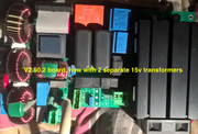
My guess would be the transformer referred to earlier in this thread as T1 by Stevews; the voltage sensing transformer. In the attached pic it is the dark blue box to the left i think. the orange box at the top is the 5v logic supply.
My guess would be the transformer referred to earlier in this thread as T1 by Stevews; the voltage sensing transformer. In the attached pic it is the dark blue box to the left i think. the orange box at the top is the 5v logic supply.
450W hydro-electric
5110W pv
1.3kw Wt2 - not yet producing
6kWh lead acid - maybe 1kwh useable
LiMnCo battery made from 2nd hand hybrid car modules 3.6kwh nominal 24v.
300lt hot water tank and two storage heaters
ASHP Grant Aerona 3 10.5kw and UFH
5110W pv
1.3kw Wt2 - not yet producing
6kWh lead acid - maybe 1kwh useable
LiMnCo battery made from 2nd hand hybrid car modules 3.6kwh nominal 24v.
300lt hot water tank and two storage heaters
ASHP Grant Aerona 3 10.5kw and UFH