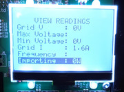
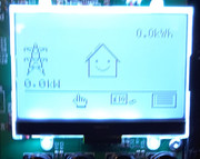
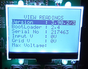
Unfortunately once a factory reset has been carried out all the existing data will been lost forever. The unit won’t display the time and date until its been entered via the menus or after it connects to the Immersuns website. I use the former method as the Immersuns website servers tend to have an incorrect time. I’ve just posted a reply to your question about the T1 transformer which I hope will be useful,joeirish wrote: ↑Sun Nov 13, 2022 5:47 pm I'm new on this forum but I have a related problem. I started to see an Error 9 Under Voltage message today. The unit had stopped working properly yesterday (not showing an input from the inverter or any export to the grid etc, pic attached) so today I did a factory reset. Then when I selected the heater it displayed this error and would not proceed with the start up. I then re-started holding down the X button to force a normal run but it is still not working. All the savings data from the past six years has disappeared, it is now showing 0.00. But it still has the date and the tariff correct. Some of the items on the top line of the display (date and time, savings etc) are not showing. I've had a good look inside the unit and no sign of any burn marks on any of the components or the PCB. Not sure if anybody has any ideas. I see an earlier post where somebody said the replaced T1 but I'm not sure which this is and I've never done any electronic stuff. Also attached are some screens from the Readings menu. I;m sure some of the 0 values are not what should be there? Thanks.
PS I live in Ireland so not easy to get it back to be repaired even if this were possible.
immersun repair -no.3
Re: immersun repair -no.3
Re: immersun repair -no.3
Thanks Steve. I think I'll be getting somebody who is ofay with soldering such things to swap them over. I've the whole thing dismantled and it looks very complicated. Not even sure how many prongs there are but looking but hopefully somebody with expertise will be able to do this. Cheers.Stevews wrote: ↑Mon Nov 14, 2022 11:13 am Hi Joeirish,
You are correct, the T1 transformers used in the Immersun Units were made in Italy. I found it impossible to source a replacement anywhere in the UK and after a lot of research I found the following supplier. The link also gives the part number you need. The price for the unit is the same as I paid a few months ago. Postage charges are reasonable and quick.
https://store.open-electronics.org/inde ... -SVL101201
When you desolder the existing T1 transformer just be careful as the prongs are a lot thicker compared to other components and need more heat to remove thr existing solder. Being patient and using the right tools helps a lot.
I hope this helps and resolves your problem. Let us know how you get on.
Steve
Re: immersun repair -no.3
Hi,joeirish wrote: ↑Mon Nov 14, 2022 10:31 pmThanks Steve. I think I'll be getting somebody who is ofay with soldering such things to swap them over. I've the whole thing dismantled and it looks very complicated. Not even sure how many prongs there are but looking but hopefully somebody with expertise will be able to do this. Cheers.Stevews wrote: ↑Mon Nov 14, 2022 11:13 am Hi Joeirish,
You are correct, the T1 transformers used in the Immersun Units were made in Italy. I found it impossible to source a replacement anywhere in the UK and after a lot of research I found the following supplier. The link also gives the part number you need. The price for the unit is the same as I paid a few months ago. Postage charges are reasonable and quick.
https://store.open-electronics.org/inde ... -SVL101201
When you desolder the existing T1 transformer just be careful as the prongs are a lot thicker compared to other components and need more heat to remove thr existing solder. Being patient and using the right tools helps a lot.
I hope this helps and resolves your problem. Let us know how you get on.
Steve
I don’t have much electronics experience but have successfully managed to replace a few components on my Immersun unit.
I’ve attached a couple of photos of the T1 transformer for reference, as you can see it has 6 prongs. The new transformer is on the left and you can see how it compares to the one I replaced it with, which had some brown staining on the underside.
- Attachments
-
- B9B694A4-8EB1-4253-9F7B-2D7936380498.jpeg (77.55 KiB) Viewed 4018 times
-
- E46AA062-A365-4047-8FE9-FD8F9510CD74.jpeg (70.41 KiB) Viewed 4018 times
Re: immersun repair -no.3
SteveStevews wrote: ↑Mon Nov 14, 2022 11:13 am
Hi,
I don’t have much electronics experience but have successfully managed to replace a few components on my Immersun unit.
I’ve attached a couple of photos of the T1 transformer for reference, as you can see it has 6 prongs. The new transformer is on the left and you can see how it compares to the one I replaced it with, which had some brown staining on the underside.
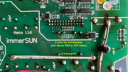
Thanks again, this is really helpful. So do you think I could manage to do this myself? I suppose I have to get the solder off the back of the board where the prongs come through then somehow pull off the old unit, clean all the holes and solder in the new one. Sounds fairly easy but the back seems very cluttered around where the side with the 4 prongs come through. Seem to be lots of little transistors (?) next to those 4 solder points. I'm attaching a photo. Did you have any issues and how did you remove the old solder etc. My worry would be that I might damage the row of little transistors. Cheers. Joe
-
Countrypaul
- Posts: 473
- Joined: Sun Jul 18, 2021 11:50 am
Re: immersun repair -no.3
I've used a solder pump to remove components for replacement on such things as Xbox controllers. The pump normally cost less than £5 and are readily available. You heat the solder with an iron and soonas it melts suck the molten solder out with the pump. It takes a little practice so if you go this route I suggest trying on some scrap boards to get the hang of it. Make sure you don't overheat anything or touch those surface mounted components.
Last edited by Countrypaul on Tue Nov 15, 2022 5:47 pm, edited 1 time in total.

Re: immersun repair -no.3
I prefer to use "desoldering braid", even cheaper and still effective. But again, its also worth doing a bit of practise on some scrap board first if you've never used it.
15.2kW PV > 100MWh generated
Ripple 6.6kW Wind + 4.5kW PV > 19MWh generated
5 Other RE Coop's
105kWh EV storage
60kWh Home battery storage
40kWh Thermal storage
GSHP + A2A HP's
Rain water use > 490 m3
Ripple 6.6kW Wind + 4.5kW PV > 19MWh generated
5 Other RE Coop's
105kWh EV storage
60kWh Home battery storage
40kWh Thermal storage
GSHP + A2A HP's
Rain water use > 490 m3
Re: immersun repair -no.3
Hi Joe,joeirish wrote: ↑Tue Nov 15, 2022 4:09 pmSteveStevews wrote: ↑Mon Nov 14, 2022 11:13 am
Hi,
I don’t have much electronics experience but have successfully managed to replace a few components on my Immersun unit.
I’ve attached a couple of photos of the T1 transformer for reference, as you can see it has 6 prongs. The new transformer is on the left and you can see how it compares to the one I replaced it with, which had some brown staining on the underside.
Thanks again, this is really helpful. So do you think I could manage to do this myself? I suppose I have to get the solder off the back of the board where the prongs come through then somehow pull off the old unit, clean all the holes and solder in the new one. Sounds fairly easy but the back seems very cluttered around where the side with the 4 prongs come through. Seem to be lots of little transistors (?) next to those 4 solder points. I'm attaching a photo. Did you have any issues and how did you remove the old solder etc. My worry would be that I might damage the row of little transistors. Cheers. Joe
I must admit it wasn’t easy to remove and I accidentally removed the copper eyelets by mistake. I thought I had done irreversible damage but after some research I learnt that you can replace the eyelets, which I did. At the time I was using a soldering iron to heat the solder and desoldering tape to remove the solder. It’s a very tight spot,as you said, and I couldn’t get the angle right which is why I had a problem with removing some of the prongs.
There’s lots of YouTube videos showing you various techniques. As other have said it’s important to practice on a spare PCB.
In the end I purchased a dedicated desoldering gun that sucks the solder into a tube whilst melting the solder at the same time. They aren’t cheap, I think I paid about £60 for mine a few months ago. I’ve since used it to remove other components from other devices so for me it was a worthwhile purchase.
Just be very careful and take your time and don’t force the pins from the PCB, otherwise you will definitely damage the eyelets, that’s how I lost mine.
Here’s a a few pics showing what I mean by eyelets. They look like rivets and are normally made of copper.
When I replaced the T1 Transformer I used a mixed solder 60/40 as it has a lower melting point but be careful as it contains lead. I also used liquid flux which I applied using a syringe type device. It’s more accurate that way. Don’t forget to use isopropyl alcohol to remove any residual flux once you’ve finished soldering.
Have you had any experience with soldering and desoldering?
If I can help in way let me know.
Steve
- Attachments
-
- 50D9B800-3010-4F8A-8378-63211C49F995.jpeg (32.36 KiB) Viewed 3976 times
-
- F649B3A4-442E-4C2C-A4A4-ED3E83C0D333.jpeg (35.52 KiB) Viewed 3976 times
-
- CE3B3C97-E822-443A-937C-AEA762B82629.jpeg (32.22 KiB) Viewed 3976 times
Re: immersun repair -no.3
HiStevews wrote: ↑Tue Nov 15, 2022 7:47 pm
Hi Joe,
I must admit it wasn’t easy to remove and I accidentally removed the copper eyelets by mistake. I thought I had done irreversible damage but after some research I learnt that you can replace the eyelets, which I did. At the time I was using a soldering iron to heat the solder and desoldering tape to remove the solder. It’s a very tight spot,as you said, and I couldn’t get the angle right which is why I had a problem with removing some of the prongs.
There’s lots of YouTube videos showing you various techniques. As other have said it’s important to practice on a spare PCB.
In the end I purchased a dedicated desoldering gun that sucks the solder into a tube whilst melting the solder at the same time. They aren’t cheap, I think I paid about £60 for mine a few months ago. I’ve since used it to remove other components from other devices so for me it was a worthwhile purchase.
Just be very careful and take your time and don’t force the pins from the PCB, otherwise you will definitely damage the eyelets, that’s how I lost mine.
Here’s a a few pics showing what I mean by eyelets. They look like rivets and are normally made of copper.
When I replaced the T1 Transformer I used a mixed solder 60/40 as it has a lower melting point but be careful as it contains lead. I also used liquid flux which I applied using a syringe type device. It’s more accurate that way. Don’t forget to use isopropyl alcohol to remove any residual flux once you’ve finished soldering.
Have you had any experience with soldering and desoldering?
If I can help in way let me know.
Steve
Just a final update. I had a friend swap the transformers and just re-connected everything. All working now. It was a real faff remiving the old T1 transformer but he managed it in the end. Thanks for all the help.
Joe
Re: immersun repair -no.3
Good to hear that another unit has been repaired rather than binned.joeirish wrote: ↑Mon Dec 05, 2022 4:14 pmHiStevews wrote: ↑Tue Nov 15, 2022 7:47 pm
Hi Joe,
I must admit it wasn’t easy to remove and I accidentally removed the copper eyelets by mistake. I thought I had done irreversible damage but after some research I learnt that you can replace the eyelets, which I did. At the time I was using a soldering iron to heat the solder and desoldering tape to remove the solder. It’s a very tight spot,as you said, and I couldn’t get the angle right which is why I had a problem with removing some of the prongs.
There’s lots of YouTube videos showing you various techniques. As other have said it’s important to practice on a spare PCB.
In the end I purchased a dedicated desoldering gun that sucks the solder into a tube whilst melting the solder at the same time. They aren’t cheap, I think I paid about £60 for mine a few months ago. I’ve since used it to remove other components from other devices so for me it was a worthwhile purchase.
Just be very careful and take your time and don’t force the pins from the PCB, otherwise you will definitely damage the eyelets, that’s how I lost mine.
Here’s a a few pics showing what I mean by eyelets. They look like rivets and are normally made of copper.
When I replaced the T1 Transformer I used a mixed solder 60/40 as it has a lower melting point but be careful as it contains lead. I also used liquid flux which I applied using a syringe type device. It’s more accurate that way. Don’t forget to use isopropyl alcohol to remove any residual flux once you’ve finished soldering.
Have you had any experience with soldering and desoldering?
If I can help in way let me know.
Steve
Just a final update. I had a friend swap the transformers and just re-connected everything. All working now. It was a real faff remiving the old T1 transformer but he managed it in the end. Thanks for all the help.
Joe
3.87kWp PV
10.24kWp PV SolarEdge system
Tesla Powerwall 2
100 x 47mm Navitron tubes (still being installed!) Now likely to be removed for more PV.
MK2 PV router DHW diverter
Morso 5kW WBS
Vaillant AroTherm 10kW ASHP
Nissan Leaf
10.24kWp PV SolarEdge system
Tesla Powerwall 2
100 x 47mm Navitron tubes (still being installed!) Now likely to be removed for more PV.
MK2 PV router DHW diverter
Morso 5kW WBS
Vaillant AroTherm 10kW ASHP
Nissan Leaf
-
Oldgreybeard
- Posts: 1873
- Joined: Thu Sep 09, 2021 3:42 pm
- Location: North East Dorset
Re: immersun repair -no.3
Excellent result. It's always great to be able to fix something, rather than bin it. I've spent a happy (!) hour this afternoon fixing the Optima controller for our MVHR. It kept blanking the screen and resetting when one of the buttons was pressed (didn't matter which one). A new Optima 300 controller is a rather scary £343 +VAT and shipping, so I took it off the wall this afternoon, removed the SD card, managed to get the case to pop open and found the fix was dead easy, a simple dry joint on the 4 way connector that the power and RS485 data cable from the MVHR connects to.
Seems to be commonplace now for solder to just go brittle and crack with age. I think it's something to do with the introduction of lead-free solder. It's a good idea to reduce the use of lead, but the lead-free stuff isn't syntactic, so is more prone to cracking. Needless to say all four solder joints are now remade with nice and solid 60/40 tin lead. I'm 70 now, so I'll live with the tiny risk of lead poisoning . . .
25 off 250W Perlight solar panels, installed 2014, with a 6kW PowerOne inverter, about 6,000kWh/year generated
6 off Pylontech US3000C batteries, with a Sofar ME3000SP inverter
6 off Pylontech US3000C batteries, with a Sofar ME3000SP inverter