FET's have been removed so cant be them.
Think I'll try to isolate pin 5 on the opto and see if the voltage comes back up.
Electronics help required with Sofar ME3000SP
Re: Electronics help required with Sofar ME3000SP
85no 58mm solar thermal tubes, 28.5Kw PV, 3x Sunny Island 5048, 2795 Ah (135kWh) (c20) Rolls batteries 48v, 8kWh Growatt storage, 22 x US3000C Pylontech, Sofar ME3000's, Brosley wood burner and 250lt DHW
Re: Electronics help required with Sofar ME3000SP
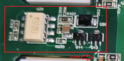
Just measured the voltage across D58 and it's about 11v. (Not isolated the opto).
The same diode on the working fets has 0v across it.
That shouldn't happen should it.
Edit that's the supply to the opto though resistor R407 (4R70)
The same diode on the working fets has 0v across it.
That shouldn't happen should it.
Edit that's the supply to the opto though resistor R407 (4R70)
85no 58mm solar thermal tubes, 28.5Kw PV, 3x Sunny Island 5048, 2795 Ah (135kWh) (c20) Rolls batteries 48v, 8kWh Growatt storage, 22 x US3000C Pylontech, Sofar ME3000's, Brosley wood burner and 250lt DHW
Re: Electronics help required with Sofar ME3000SP
Oh, ok, if it's 11v across the diode and 0.6 across pins 5 and 8 then yes it does look like the opto is shorted 
450W hydro-electric
5110W pv
1.3kw Wt2 - not yet producing
6kWh lead acid - maybe 1kwh useable
LiMnCo battery made from 2nd hand hybrid car modules 3.6kwh nominal 24v.
300lt hot water tank and two storage heaters
ASHP Grant Aerona 3 10.5kw and UFH
5110W pv
1.3kw Wt2 - not yet producing
6kWh lead acid - maybe 1kwh useable
LiMnCo battery made from 2nd hand hybrid car modules 3.6kwh nominal 24v.
300lt hot water tank and two storage heaters
ASHP Grant Aerona 3 10.5kw and UFH
Re: Electronics help required with Sofar ME3000SP
I've just isolated the pin 5 on the opto and strangely I'm still getting the same trace on the oscilloscope for the FET gate. Pretty well wherever I put a probe on anything within the red box except to the right of the D58 and left of the opto I get the same trace. Even on pin 8 of the opto. (On pins 2 and 3 the trace is a nice square wave). I also still get the 11v voltage difference across D58.
I'm a little baffled.
I'm a little baffled.
85no 58mm solar thermal tubes, 28.5Kw PV, 3x Sunny Island 5048, 2795 Ah (135kWh) (c20) Rolls batteries 48v, 8kWh Growatt storage, 22 x US3000C Pylontech, Sofar ME3000's, Brosley wood burner and 250lt DHW
Re: Electronics help required with Sofar ME3000SP
And your using the source of the relevant fets or the pin5 pad as a ground reference for the scope measurement?Tinbum wrote: ↑Thu Aug 31, 2023 10:50 pm I've just isolated the pin 5 on the opto and strangely I'm still getting the same trace on the oscilloscope for the FET gate. Pretty well wherever I put a probe on anything within the red box except to the right of the D58 and left of the opto I get the same trace. Even on pin 8 of the opto. (On pins 2 and 3 the trace is a nice square wave). I also still get the 11v voltage difference across D58.
I'm a little baffled.
What are the two ends of D58 connected to?
450W hydro-electric
5110W pv
1.3kw Wt2 - not yet producing
6kWh lead acid - maybe 1kwh useable
LiMnCo battery made from 2nd hand hybrid car modules 3.6kwh nominal 24v.
300lt hot water tank and two storage heaters
ASHP Grant Aerona 3 10.5kw and UFH
5110W pv
1.3kw Wt2 - not yet producing
6kWh lead acid - maybe 1kwh useable
LiMnCo battery made from 2nd hand hybrid car modules 3.6kwh nominal 24v.
300lt hot water tank and two storage heaters
ASHP Grant Aerona 3 10.5kw and UFH
Re: Electronics help required with Sofar ME3000SP
The right of D58 goes through the board and i've yet to take it out again. Will do tomorrow.
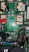
This is the circuit diag i've done so far. Circles with cross go through the board.
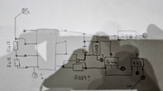
Ground is the source for the FET.
The traces for the FET gates on the left side of the board look different to the traces on the right that I did earlier. (right side switch the - | left side switch the +) The right side also doesn't have diodes like D58.
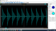
This is a trace for the + that's working;
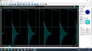
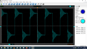
This is the trace for the + that's faulty; (pin 5 isolated)
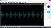
This is the trace for the + that's not working on the right of Diode 58.
I'm going to check all the above again tomorrow when I'm a little more awake. (The cats being a dirty stop out and i dont like to go to bed until he's in).
85no 58mm solar thermal tubes, 28.5Kw PV, 3x Sunny Island 5048, 2795 Ah (135kWh) (c20) Rolls batteries 48v, 8kWh Growatt storage, 22 x US3000C Pylontech, Sofar ME3000's, Brosley wood burner and 250lt DHW
Re: Electronics help required with Sofar ME3000SP
Yes I'm off to bed now (the cats there ahead of me).
Sorry if i'm sort of labouring the point of the ground reference for your measurements, but the voltages on the scope traces of the left side fets suggest that you're possibly using the battery -ve as zero, which will work for the right side fets but not for the left - although i may be misinterpreting the volt settings. To make sense of the voltages on the left side fets, the 0v reference for the measurements must be the sources of the same two fets whose gates your testing (or pin5 of their own opto-isolator).
Looking at your diagram, i do think that q44 and q43 are totem pole drivers: q44 possibly a p-fet and q43 a n-fet, if so the drains(?) (right hand legs) are connected to each other and go to the fet gates, and the bottom of c258 (gate supply -ve) goes to the middle contacts (source?) of q43. Maybe.
450W hydro-electric
5110W pv
1.3kw Wt2 - not yet producing
6kWh lead acid - maybe 1kwh useable
LiMnCo battery made from 2nd hand hybrid car modules 3.6kwh nominal 24v.
300lt hot water tank and two storage heaters
ASHP Grant Aerona 3 10.5kw and UFH
5110W pv
1.3kw Wt2 - not yet producing
6kWh lead acid - maybe 1kwh useable
LiMnCo battery made from 2nd hand hybrid car modules 3.6kwh nominal 24v.
300lt hot water tank and two storage heaters
ASHP Grant Aerona 3 10.5kw and UFH
-
ALAN/ALAN D
Re: Electronics help required with Sofar ME3000SP
Have you thought that the Cat might be outside in the early hours waiting for the Space Station to come over. 
You could try just shining a torch out the window to confuse it a bit.
Downside is that the Mosquitoes might come in when you open the window.
You could try just shining a torch out the window to confuse it a bit.
Downside is that the Mosquitoes might come in when you open the window.
Re: Electronics help required with Sofar ME3000SP
That's fineMarcus wrote: ↑Fri Sep 01, 2023 2:13 am
Sorry if i'm sort of labouring the point of the ground reference for your measurements, but the voltages on the scope traces of the left side fets suggest that you're possibly using the battery -ve as zero, which will work for the right side fets but not for the left - although i may be misinterpreting the volt settings. To make sense of the voltages on the left side fets, the 0v reference for the measurements must be the sources of the same two fets whose gates your testing (or pin5 of their own opto-isolator).
EDIT- no i'm not
I'll have to check if pin 5 is actually connected to the +.
I'm just about to remove the PCB again so will update.Marcus wrote: ↑Fri Sep 01, 2023 2:13 am Looking at your diagram, i do think that q44 and q43 are totem pole drivers: q44 possibly a p-fet and q43 a n-fet, if so the drains(?) (right hand legs) are connected to each other and go to the fet gates, and the bottom of c258 (gate supply -ve) goes to the middle contacts (source?) of q43. Maybe.
This is the trace across the 2 output terminals.
Last edited by Tinbum on Fri Sep 01, 2023 4:02 pm, edited 1 time in total.
85no 58mm solar thermal tubes, 28.5Kw PV, 3x Sunny Island 5048, 2795 Ah (135kWh) (c20) Rolls batteries 48v, 8kWh Growatt storage, 22 x US3000C Pylontech, Sofar ME3000's, Brosley wood burner and 250lt DHW
Re: Electronics help required with Sofar ME3000SP
Pin 5 is connected to the lower output.
(Pin 5 on the other + fets is connected to the upper output and the pin 5 for the - fets are all connected to the - battery.)
I'm going to do the traces again. I can't belief i got the ground wrong. I just didn't think of the output being the souce despite me drawing it on the DC circuit diagram at the very beginning of this tread.
85no 58mm solar thermal tubes, 28.5Kw PV, 3x Sunny Island 5048, 2795 Ah (135kWh) (c20) Rolls batteries 48v, 8kWh Growatt storage, 22 x US3000C Pylontech, Sofar ME3000's, Brosley wood burner and 250lt DHW