ALAN/ALAN D wrote: ↑Fri Sep 01, 2023 10:51 am Have you thought that the Cat might be outside in the early hours waiting for the Space Station to come over.
You could try just shining a torch out the window to confuse it a bit.
Downside is that the Mosquitoes might come in when you open the window.
Electronics help required with Sofar ME3000SP
Re: Electronics help required with Sofar ME3000SP
85no 58mm solar thermal tubes, 28.5Kw PV, 3x Sunny Island 5048, 135kWh Rolls batteries, 52kWh Growatt storage GBLI 6532, 66kWh Pylontech US3000C, 43kWh DIY, Sofar ME3000's, Brosley wood burner and 250lt DHW
Re: Electronics help required with Sofar ME3000SP
Tinbum wrote: ↑Fri Sep 01, 2023 1:31 pm Pin 5 is connected to the lower output.
(Pin 5 on the other + fets is connected to the upper output and the pin 5 for the - fets are all connected to the - battery.)
I'm going to do the traces again. I can't belief i got the ground wrong. I just didn't think of the output being the souce despite me drawing it on the DC circuit diagram at the very beginning of this tread.
450W hydro-electric
5110W pv
1.3kw Wt2 - not yet producing
6kWh lead acid - maybe 1kwh useable
LiMnCo battery made from 2nd hand hybrid car modules 3.6kwh nominal 24v.
300lt hot water tank and two storage heaters
ASHP Grant Aerona 3 10.5kw and UFH
5110W pv
1.3kw Wt2 - not yet producing
6kWh lead acid - maybe 1kwh useable
LiMnCo battery made from 2nd hand hybrid car modules 3.6kwh nominal 24v.
300lt hot water tank and two storage heaters
ASHP Grant Aerona 3 10.5kw and UFH
Re: Electronics help required with Sofar ME3000SP
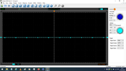
This is making more sense now.
Negative side top and bottom Gate;

positive top gate working;

positive non working gate; (opto 5 disconnected and connected the same)

right of Diode on the working fets +
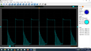
right of diode 58 (non working Fets);
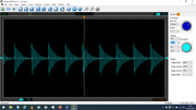
left of diode working fets +
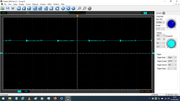
left of D58 non working fets (opto 5 disconnected and connected the same)
85no 58mm solar thermal tubes, 28.5Kw PV, 3x Sunny Island 5048, 135kWh Rolls batteries, 52kWh Growatt storage GBLI 6532, 66kWh Pylontech US3000C, 43kWh DIY, Sofar ME3000's, Brosley wood burner and 250lt DHW
Re: Electronics help required with Sofar ME3000SP
Just come across this for a Hybrid inverter that you may be interested in.
https://powerforum.co.za/files/file/157 ... 9e2f961389
https://powerforum.co.za/files/file/157 ... 9e2f961389
85no 58mm solar thermal tubes, 28.5Kw PV, 3x Sunny Island 5048, 135kWh Rolls batteries, 52kWh Growatt storage GBLI 6532, 66kWh Pylontech US3000C, 43kWh DIY, Sofar ME3000's, Brosley wood burner and 250lt DHW
Re: Electronics help required with Sofar ME3000SP
What I think is the circuit diagram. (edit Oooop's cant quite be as Drain connected to S)
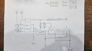
Last edited by Tinbum on Fri Sep 01, 2023 7:06 pm, edited 1 time in total.
85no 58mm solar thermal tubes, 28.5Kw PV, 3x Sunny Island 5048, 135kWh Rolls batteries, 52kWh Growatt storage GBLI 6532, 66kWh Pylontech US3000C, 43kWh DIY, Sofar ME3000's, Brosley wood burner and 250lt DHW
Re: Electronics help required with Sofar ME3000SP
Ok, back from work.
Bit fuzzy headed tho'. They make some sense, mostly , but looking at the working high side diode:-
The the right of the working diode goes from +13ish to -50ish relative to the sources/pin5 i assume. This is giving me some trouble: it sort of makes sense - i think: when its fets (high side ) turn on the sources rise to b+ (+50v??), so if the right of the diode is connected to something at b- you would see -50 on the scope.
When the high side turns off (and the low side turns on ) the sources are pulled down to b-, at which point the right of the diode rises to 13v above b-
My impression is that the diodes and the 4r7 (R407 - that's confusing) are parts of a 'bootstrap ' circuit used to produce the 13v highside gate drive supplies but I'm not quite seeing how it works yet...
The implication though is that we ought to see some +ve voltage on D58's right side - at lease 50% of the time, when the low side fets are on. Even if there's a short on the gate drive we should see some voltage drop across R407 and the diode, I'm thinking.
450W hydro-electric
5110W pv
1.3kw Wt2 - not yet producing
6kWh lead acid - maybe 1kwh useable
LiMnCo battery made from 2nd hand hybrid car modules 3.6kwh nominal 24v.
300lt hot water tank and two storage heaters
ASHP Grant Aerona 3 10.5kw and UFH
5110W pv
1.3kw Wt2 - not yet producing
6kWh lead acid - maybe 1kwh useable
LiMnCo battery made from 2nd hand hybrid car modules 3.6kwh nominal 24v.
300lt hot water tank and two storage heaters
ASHP Grant Aerona 3 10.5kw and UFH
Re: Electronics help required with Sofar ME3000SP
Revised diagram.
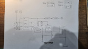
Last edited by Tinbum on Fri Sep 01, 2023 8:22 pm, edited 1 time in total.
85no 58mm solar thermal tubes, 28.5Kw PV, 3x Sunny Island 5048, 135kWh Rolls batteries, 52kWh Growatt storage GBLI 6532, 66kWh Pylontech US3000C, 43kWh DIY, Sofar ME3000's, Brosley wood burner and 250lt DHW
Re: Electronics help required with Sofar ME3000SP
I'm not quite sure where the right of diode 58 goes to. The PCB looks to have 3 layers of tracks and that one is in the centre one. It does look to connect to the - side gate control circuitry at capacitor C249 and Q 39. Also to C267 on the upper - fet gate control It then goes off to the D51 on the + fet gate control. I think it does have a leg to somewhere else on the main board but it's hidden by the upper pcb tracks.Marcus wrote: ↑Fri Sep 01, 2023 7:04 pm Ok, back from work.
Bit fuzzy headed tho'. They make some sense, mostly , but looking at the working high side diode:-
The the right of the working diode goes from +13ish to -50ish relative to the sources/pin5 i assume. This is giving me some trouble: it sort of makes sense - i think: when its fets (high side ) turn on the sources rise to b+ (+50v??), so if the right of the diode is connected to something at b- you would see -50 on the scope.
When the high side turns off (and the low side turns on ) the sources are pulled down to b-, at which point the right of the diode rises to 13v above b-
My impression is that the diodes and the 4r7 (R407 - that's confusing) are parts of a 'bootstrap ' circuit used to produce the 13v highside gate drive supplies but I'm not quite seeing how it works yet...
The implication though is that we ought to see some +ve voltage on D58's right side - at lease 50% of the time, when the low side fets are on. Even if there's a short on the gate drive we should see some voltage drop across R407 and the diode, I'm thinking.
EDIT
I'm going to put a new fet in the lower - side and put the pcb back in and re-run the tests. I'm wondering why the traces for the right side of the diodes are different if they are connected.
85no 58mm solar thermal tubes, 28.5Kw PV, 3x Sunny Island 5048, 135kWh Rolls batteries, 52kWh Growatt storage GBLI 6532, 66kWh Pylontech US3000C, 43kWh DIY, Sofar ME3000's, Brosley wood burner and 250lt DHW
Re: Electronics help required with Sofar ME3000SP
is the right of D58 common with the +13v on the low side gate drives then? If so it should be fairly steady +13v relative to b- . I seem to remember you saying you measured 11v there earlier?
That would make sense - that way when the low side fets are on, D58 R407 charge up the caps on the high side gate drive.
It looks like you have removed the low side fets on the faulty half of the bridge though? Without them pulling the sources of the high side to b- you aren't going to get any voltage drop so you aren't going to see any charging of the high side gate drive supply.
450W hydro-electric
5110W pv
1.3kw Wt2 - not yet producing
6kWh lead acid - maybe 1kwh useable
LiMnCo battery made from 2nd hand hybrid car modules 3.6kwh nominal 24v.
300lt hot water tank and two storage heaters
ASHP Grant Aerona 3 10.5kw and UFH
5110W pv
1.3kw Wt2 - not yet producing
6kWh lead acid - maybe 1kwh useable
LiMnCo battery made from 2nd hand hybrid car modules 3.6kwh nominal 24v.
300lt hot water tank and two storage heaters
ASHP Grant Aerona 3 10.5kw and UFH
Re: Electronics help required with Sofar ME3000SP
Yes, the fets on both sides had blown and as I didn't know which gates were faulty I left them all out. Putting one in the - side should confirm things better. I'll then remeasure the voltage at the diodes and re run the scopes..Marcus wrote: ↑Fri Sep 01, 2023 8:22 pm It looks like you have removed the low side fets on the faulty half of the bridge though? Without them pulling the sources of the high side to b- you aren't going to get any voltage drop so you aren't going to see any charging of the high side gate drive supply.
85no 58mm solar thermal tubes, 28.5Kw PV, 3x Sunny Island 5048, 135kWh Rolls batteries, 52kWh Growatt storage GBLI 6532, 66kWh Pylontech US3000C, 43kWh DIY, Sofar ME3000's, Brosley wood burner and 250lt DHW