Forgive the bad pictures but i have no way to explain the layout without lots and lots of words. I know what i am looking at just not what the technical terms are.
I do watch urban plumbers occasionally. I do have a plan, i am just unable to articulate it properly as lack the correct terms.
Because of the buffer, the system is a direct return lay out.
Not only will this be worse for flow and balancing, it has caused excessive pipe runs which can be reduced.
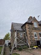
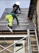
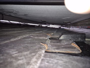
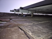
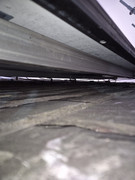
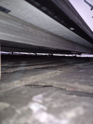
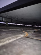
This is currently the lay out of the ASHP and the primary pipework as it runs under the suspended floor.
I dont have exact measurements only guesstimates for the length of this.
The heat pump is outside by the conservatory. The 28mm primarys do a weird loop under the conservatory into the floor void. This is about 2metres of copper outside pipe. It then travels in plastic, 2metres across the kitchen and hallway before going under the lounge. The lounge is 4x4m so hypotenuse is 5metres. So thats roughly 9 metres so far.
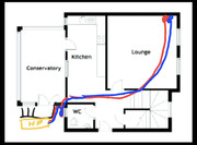
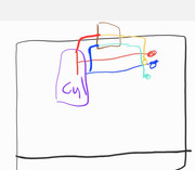
It then exits the floor void and travels up the inside of the chimney alcove (not on the drawing) in the lounge 2.4m ceilings and into the first floor.
Then keeps going up, until it gets to the loft. First floor also 2.4m high ceilings.
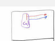
Have a good laugh at my drawing ability
So primary flow and return is 2+ 2.4 + 2.4 + 5 +2 +2=15.8 or 16metres. Very roughly.
From there the buffer tank then splits to the secondary pipework which is 22mm.
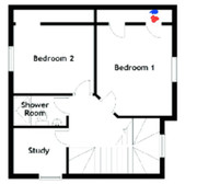
It travels down the same area to the first floor
Where it then snakes through the bedroom. And into the hallway. The radiators are in brown. The pipework obviously has the tertiary radiator pipes coming off of it.
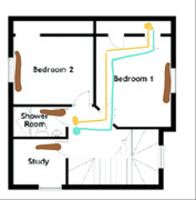
It then disappears down into the ground floor hallway, where it transitions back under the floor void, and snakes off to feed the tertiary pipes for the radiators, again shown in brown.
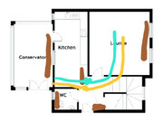
So the heating loop comes from the heatpump, under the floor, up to the loft, through the buffer, down into the bedroom across the first floor, down into the floor void, around the ground floor of the house, then back up to the loft via the first floor, only to come all the way back down to the heatpump again.
It has to do this because of the bloomin buffer, although it again could be designed much better.
My plan is to remove the buffer and second pump.
Once they are removed, i will be able to change this to a reverse return for better flow and balancing, and upgrade the pipework